Fracturing calcifications in heart valves

a technology of calcification and heart valve, which is applied in the field of percutaneous devices and methods for fracturing calcification in heart valves, can solve the problems of limited effectiveness and durability, limited leaflet mobility, and limited stretching effect, so as to increase the cross-sectional area of implanted valves, increase leaflet pliability and mobility, and increase the cross-sectional area of open valves.

Active Publication Date: 2011-05-19
PI CARDIA
View PDF21 Cites 110 Cited by
  • Summary
  • Abstract
  • Description
  • Claims
  • Application Information

AI Technical Summary

Benefits of technology

[0006]The present invention seeks to provide improved percutaneous devices and methods that may be used for fracturing calcifications in aortic valve leaflets, in order to increase leaflet pliability and mobility, thereby increasing the cross-sectional area of the open valve in patients with aortic stenosis. In addition, the devices and methods described can be applied as a preparation step for trans-catheter aortic valve implantation, in order to allow valve implantation in heavily calcified native valves, increase the cross-sectional area of the implanted valve and decrease the risk of paravalvular leaks. The devices and methods may also be designed for performing angioplasty on calcified plaque.

Problems solved by technology

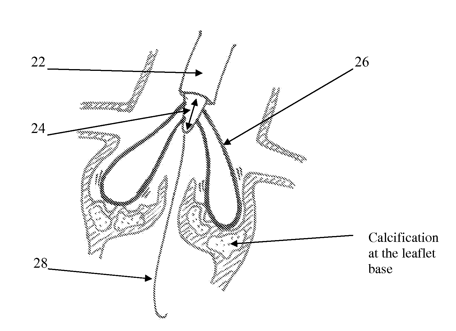
Specifically, calcification that occurs at the leaflet base, i.e., where the leaflet connects to the annulus or aortic wall, can significantly impair the mobility of the leaflet, very much like friction in a door-hinge.
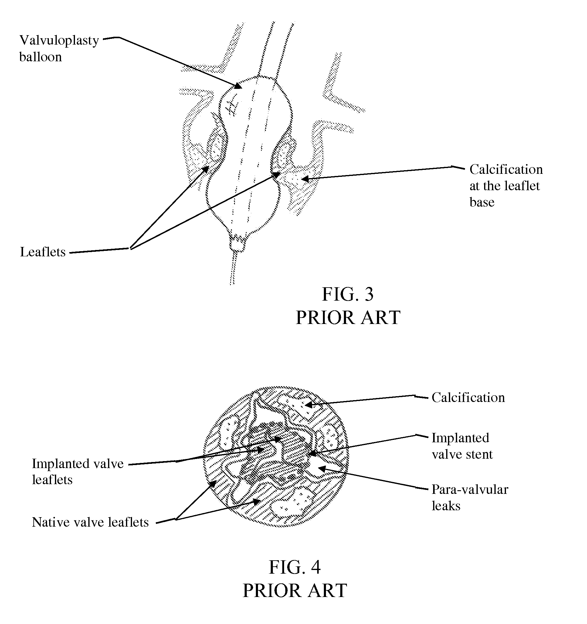
The balloon is not designed to fracture the calcification, and therefore produces only a limited “stretching” effect on the leaflets and annulus.
Such a “stretching” effect may have limited effectiveness and durability, can potentially cause tearing of the fibrous tissue that makes up most of the leaflets, and might even press the calcification against the AV node, leading to pacing complications.
When the implanted valve stent does not expand properly, the implanted valve cross-sectional area will be smaller, the coaptation of the implanted valve leaflets will be sub-optimal, and significant paravalvular leaks may occur due to the remaining gaps between the implanted valve stent and the native valve leaflets.
Each and all of these factors might significantly sacrifice the short-term and long-term outcome of the trans-catheter valve implantation procedure.

Method used


Image

  • Fracturing calcifications in heart valves
  • Fracturing calcifications in heart valves
  • Fracturing calcifications in heart valves

Examples


Embodiment Construction

[0059]Reference is now made to FIG. 5, which illustrates a percutaneous device 10 for fracturing calcifications in heart valves, in accordance with a non-limiting embodiment of the present invention. Device 10 is a catheter-based impactor device (impactor catheter) that includes an external housing 12 (shaped as a shaft, and also referred to as shaft 12) in which is housed, and from which is deployed, an impact-producing element 14. Impact-producing element 14 creates a mechanical impact when brought into contact with hard tissue. The mechanical impact is created by a rapid back and forth vibratory motion of the impact-producing element 14. The amplitude of this vibratory motion may be small (typically from less than a millimeter and up to a few millimeters), but the velocity of the impact-producing element 14 when moving in the forward direction is relatively high. Such rapid forward motion makes the impact-producing element 14 very effective in fracturing hard tissue, such as valv...


PUM


Abstract

A device for fracturing calcifications in heart valves including a catheter (12, 22, 42) configured for percutaneous delivery to a heart valve, an fracture-producing element (14, 26, 46, 64, 66,82, 124, 152) disposed at a distal portion of the catheter and operative to vibrate and mechanically fracture calcifications when brought into contact with a calcification at a leaflet of the heart valve, and an energy source (34, 47, 79, 98, 152) operative to vibrate the fracture-producing element so that the fracture-producing element fractures the calcification without necessarily removing the calcification from the leaflet. The device may further comprise a valvuloplasty balloon (30), an embolic protection net (56) and a protective sleeve (110, 130).

Description

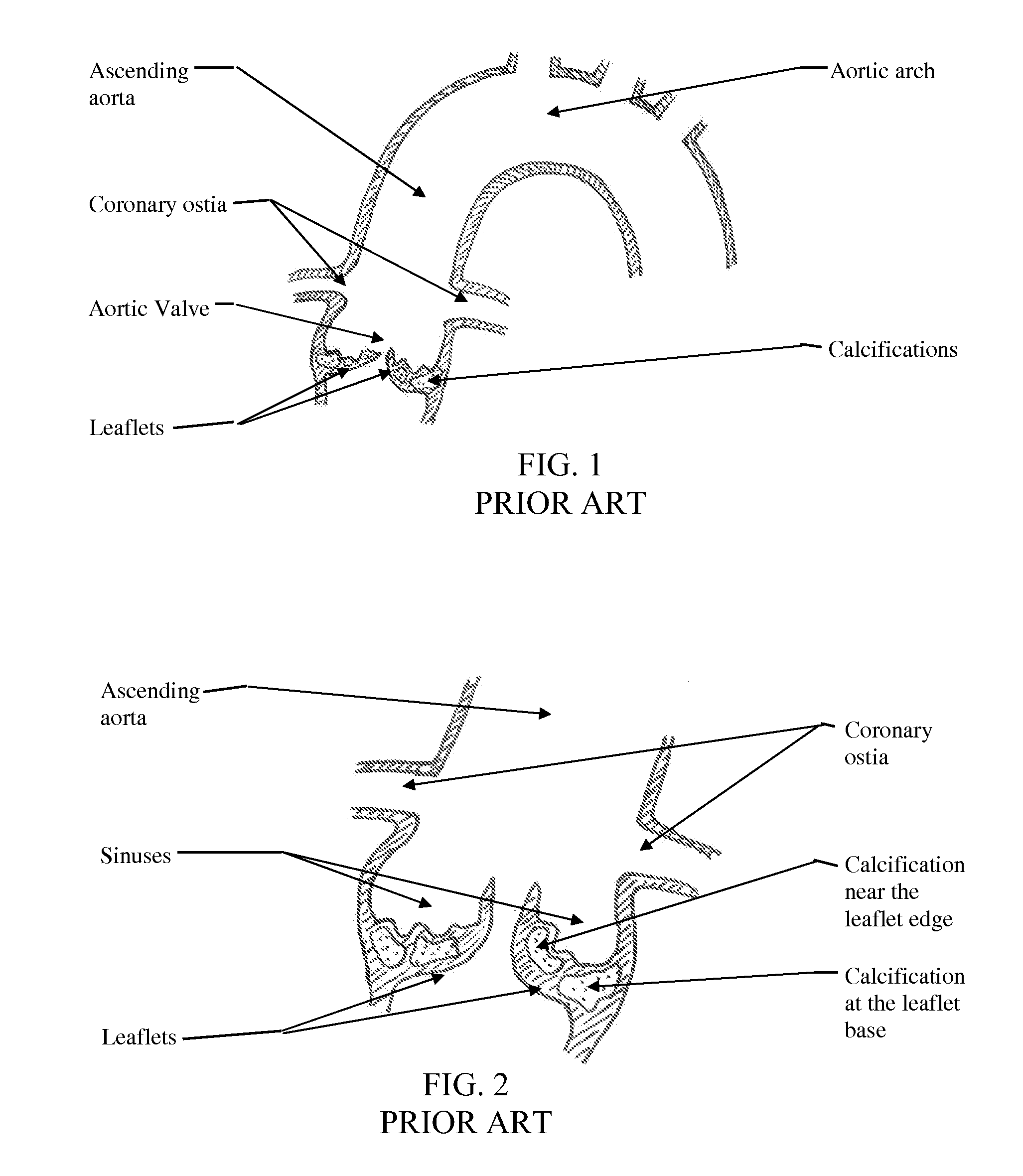
FIELD OF THE INVENTION[0001]The present invention generally relates to percutaneous devices and methods for fracturing calcifications in heart valves, such as aortic valve leaflets.BACKGROUND OF THE INVENTION[0002]Reference is made to FIG. 1, which illustrates the anatomy of a calcified aortic valve, ascending aorta and aortic arch. Calcifications may be embedded and / or superimposed on the valve leaflets, which are connected to the aortic wall just below the coronary ostia.[0003]Reference is now made to FIG. 2, which illustrates an enlarged view of a calcified aortic valve. The leaflets create concave sinuses on their aortic aspect, just below the coronary ostia. Calcification can be either embedded or superimposed on the leaflets, making the leaflets thicker and less pliable. Specifically, calcification that occurs at the leaflet base, i.e., where the leaflet connects to the annulus or aortic wall, can significantly impair the mobility of the leaflet, very much like friction in a d...

Claims


Application Information

Patent Timeline
Patent Type & Authority Applications(United States)
IPC IPC(8): A61B17/22
CPCA61B17/22012A61B17/320725A61B2017/00243A61B2017/00535A61B2017/00783A61F2/2427A61B2017/22069A61B2017/22097A61B2017/22098A61B2017/320716A61F2/2418A61B2017/22051A61B2017/22061
Inventor GOLAN, EREZ
Owner PI CARDIA
Why Eureka
Try Eureka