Image processing device, image processing system, and image processing method

a technology of image processing and image processing system, which is applied in the direction of navigation instruments, television systems, instruments, etc., can solve the problems of difficult narrowing the point where the user should be careful, the user's positional relationship is difficult to grasp, and the information to be provided to the user is excessive, so as to achieve smooth confirmation of obstacles

Active Publication Date: 2012-10-11
FUJITSU GENERAL LTD
View PDF5 Cites 48 Cited by
  • Summary
  • Abstract
  • Description
  • Claims
  • Application Information

AI Technical Summary

Benefits of technology

[0028]According to the configuration of (1) or (7), an image can be provided, from which a user can grasp the positional relationship between a vehicle and obstacles which are displayed in three dimensions as if the user saw them from above. Further, by reproducing the viewpoint movement through continuous reproduction of synthetic images that take bird's-eye views of the vehicle, the user can intuitively grasp the positional relationship between the vehicle and the obstacles.
[0029]Further, according to the configuration of (2), even if information such as the obstacles is overlooked when the viewpoint movement is displayed, it is possible to make a safety confirmation again from a position of directly above of the vehicle.
[0030]Further, according to the configuration of (3), the user can confirm the obstacles on the whole periphery of the vehicle on one screen.
[0031]Further, according to the configuration of (4), at the startup of the image processing device which is usually before the start of operation, the user can smoothly confirm the obstacles on the whole periphery of the vehicle.
[0032]Further, according to the configuration of (5), unintended shading (mechanical vignetting) can be prevented from appearing in the synthetic image, and thus the synthetic images can be provided, from which the user can intuitively grasp the positional relationship between the vehicle and the obstacles.

Problems solved by technology

However, according to the display of images of the periphery of the vehicle through the cameras in the related art, it is necessary to confirm which direction of the vehicle the images from the respective cameras correspond to, and since the user's vehicle is not displayed on the screen, it is difficult for the user to grasp the positional relationship such as the distance between the vehicle and obstacles that are present on the periphery of the vehicle.
Further, in the case of displaying the downward view that is viewed from directly above of the vehicle on the screen as the virtual viewpoint, it is necessary for the user to confirm a wide range around the whole periphery of the vehicle to cause an excessive amount of information to be provided to the user, and as a result, it is difficult to narrow the point where the user should be careful.
Further, according to the technology disclosed in Patent Document 1, since the screen that displays the viewpoint positions of the images captured by the cameras together with the overall view of the vehicle and the screen that displays the respective camera images corresponding to the movement of the viewpoint positions are displayed as separate screens, the user should perform the mapping of the information displayed on the two screens, and this causes the problem that it is difficult for the user to grasp the positional relationship between the vehicle and the obstacles.

Method used


Image

  • Image processing device, image processing system, and image processing method
  • Image processing device, image processing system, and image processing method
  • Image processing device, image processing system, and image processing method

Examples


Embodiment Construction

[0045]Hereinafter, preferred embodiments of the present invention will be described in detail with reference to the accompanying drawings.

[0046]

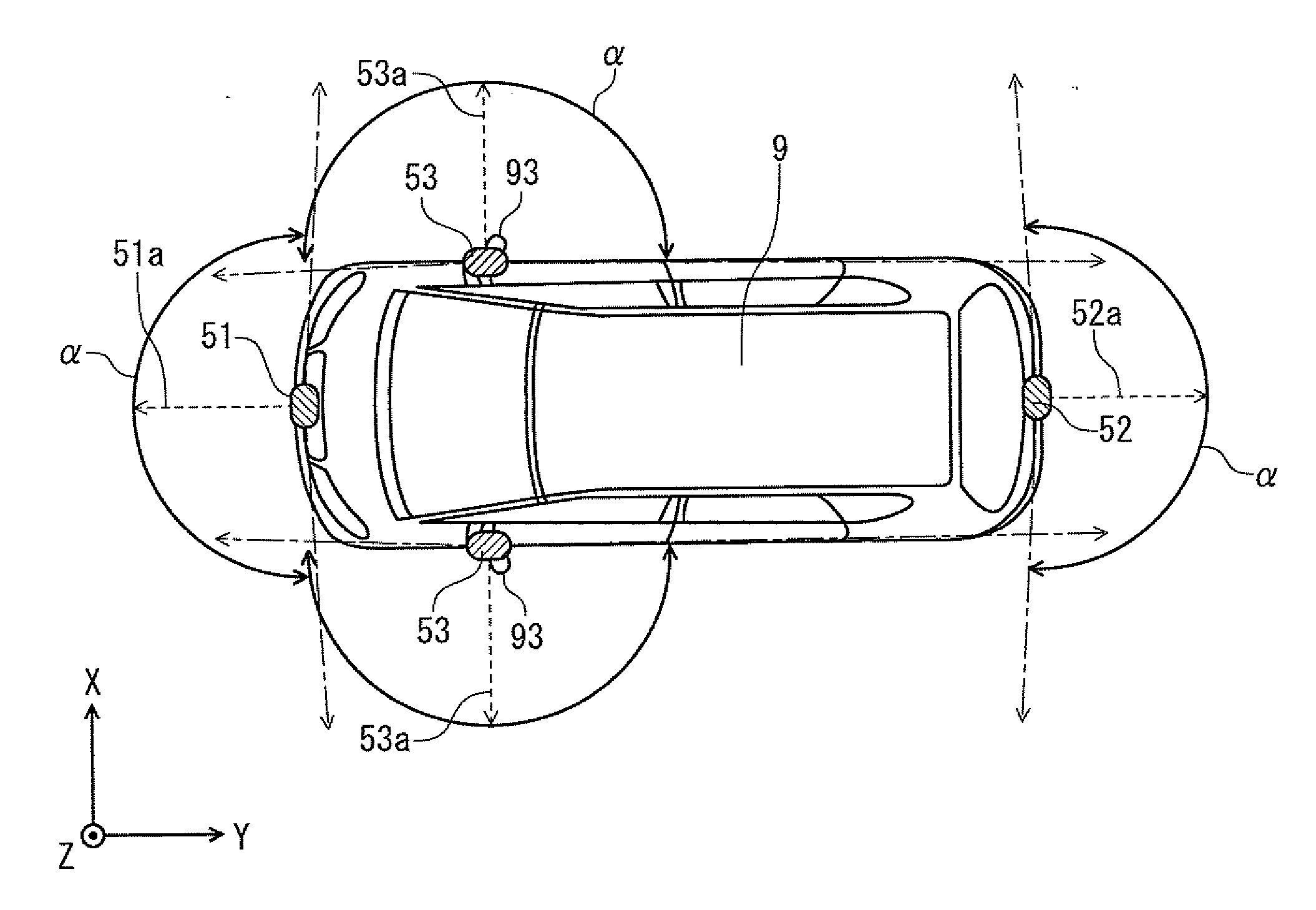
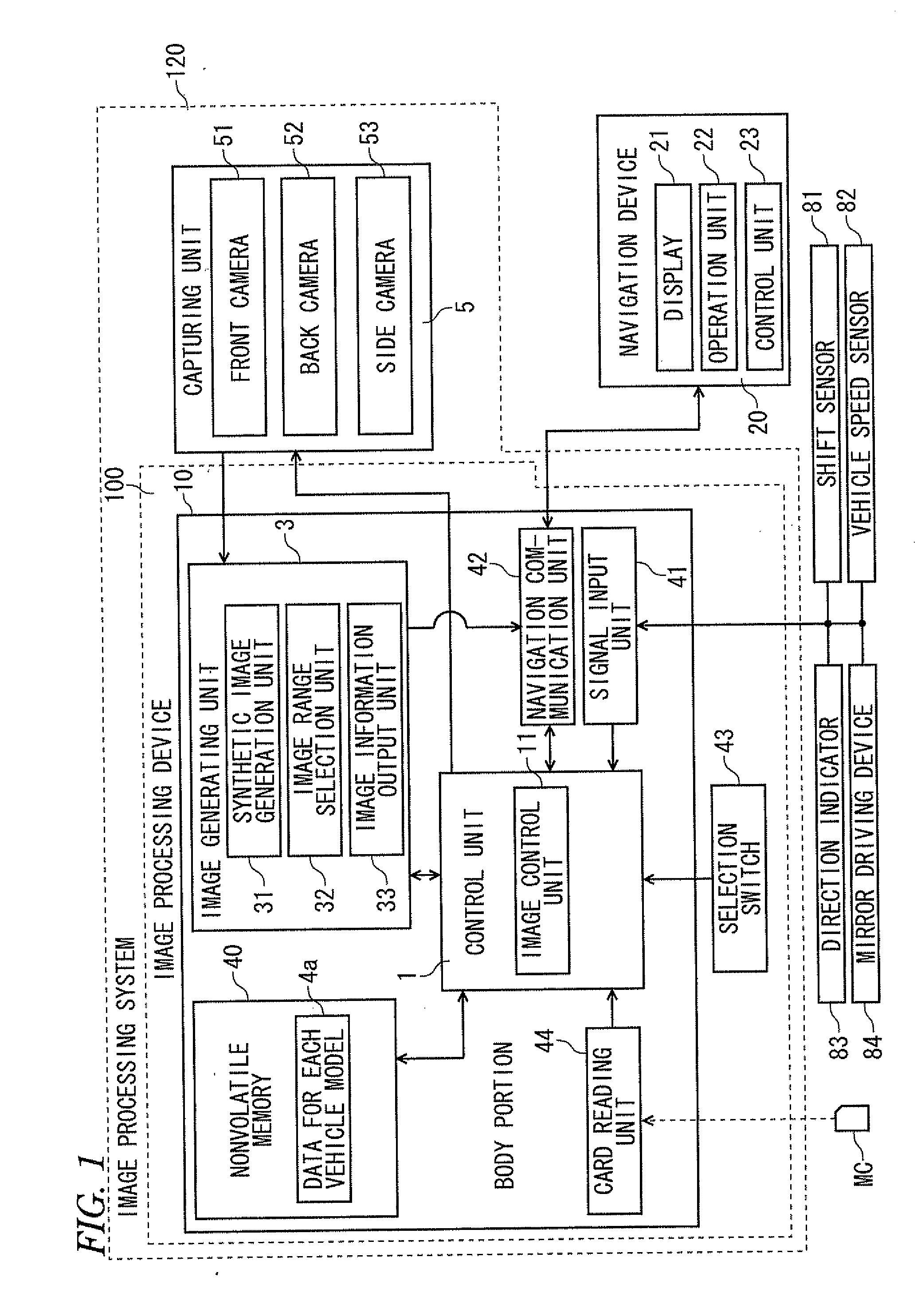
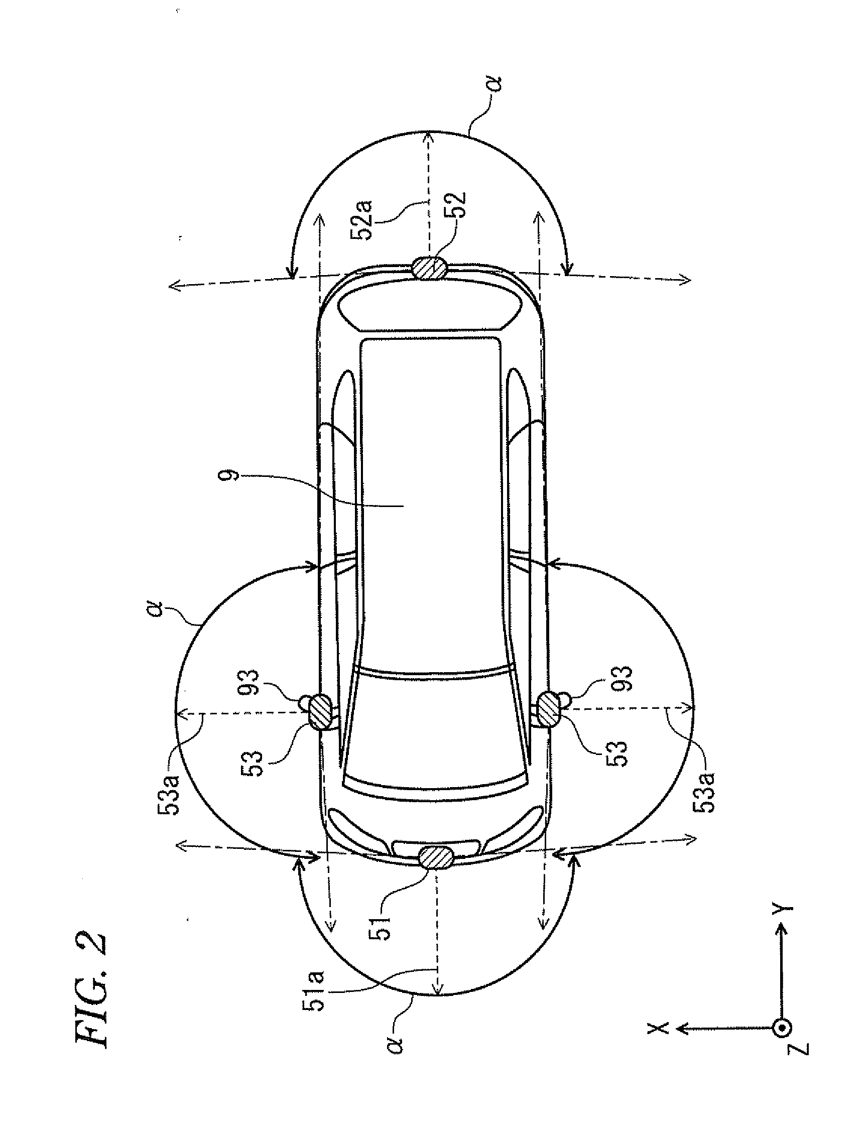
[0047]FIG. 1 is a block diagram illustrating the configuration of an image processing system 120. This image processing system 120 is installed in a vehicle (in an embodiment of the present invention, a car), and has a function of generating an image through capturing images of a periphery of a vehicle and outputting the generated image to a display device such as a navigation device 20 in a cabin. A user (representatively, a driver) of the image processing system 120 can grasp the appearance of the periphery of the vehicle substantially in real time by using the image processing system 120.

[0048]As illustrated in FIG. 1, the image processing system 120 mainly includes an image processing device 100 configured to generate peripheral images showing the periphery of the vehicle and to output image information to a display device such as a navi...


PUM


Abstract

In an image processing device configured to be installed in a vehicle, an image acquirer acquires camera images captured by cameras provided on the vehicle. A synthetic image generator generates synthetic images, which include downward views of the vehicle and a periphery thereof viewed from viewpoints different from one another, based on the camera images. A display image provider outputs, to the display device installed in the vehicle, information corresponding to a display image in which the synthetic images are continuously reproduced.

Description

TECHNICAL FIELD [0001]The present invention relates to a technology to display an image on a display device installed in a vehicle.BACKGROUND ART [0002]In general, there is a device that enables a user to monitor a periphery of a vehicle through acquiring images of the periphery of the vehicle through cameras installed on the vehicle and displaying the acquired images on a display device automatically or by a user's operation. Further, there is a device that provides a means for confirming safety around the whole periphery of a vehicle to a user through displaying a downward view that is viewed from directly above of the vehicle on a screen as a virtual viewpoint. Further, for example, Japanese Unexamined Patent Application Publication No. 2008-219559 (Patent Document 1) discloses a technology to confirm the safety around a vehicle with two screens including a first screen that displays viewpoint positions of images captured by cameras installed on the vehicle at predetermined heigh...

Claims


Application Information

Patent Timeline
Patent Type & Authority Applications(United States)
IPC IPC(8): H04N7/18
CPCH04N7/181G06T3/0012B60R2300/105G01C21/3647G08G1/165G08G1/166
Inventor KINOSHITA, KOHTAROHKOHARAZAWA, MASAHIROIMU, SUNJA
Owner FUJITSU GENERAL LTD
Why Eureka
Try Eureka