
Trailer Theft Deterrent Device

a technology for deterring devices and trailers, applied in anti-theft devices, screws, threaded fasteners, etc., can solve problems such as easy to overcome, difficult to stabilize with secondary tools, and little protection against trailer th

Inactive Publication Date: 2012-10-18
JONES CHARLES
View PDF21 Cites 13 Cited by
  • Summary
  • Abstract
  • Description
  • Claims
  • Application Information

AI Technical Summary

Benefits of technology

[0012]In view of the foregoing disadvantages inherent in the known types of trailer theft deterrents now present in the prior art, the present invention provides a new means of immobilizing a trailer that defeats many common methods for removing wheel locks, and also provides a new means for mounting a theft deterrent device to a bare hub or existing wheel to prevent trailer theft wherein the same can be utilized for providing convenience for the user when attempting to lock a trailer in place to prevent its unauthorized movement.
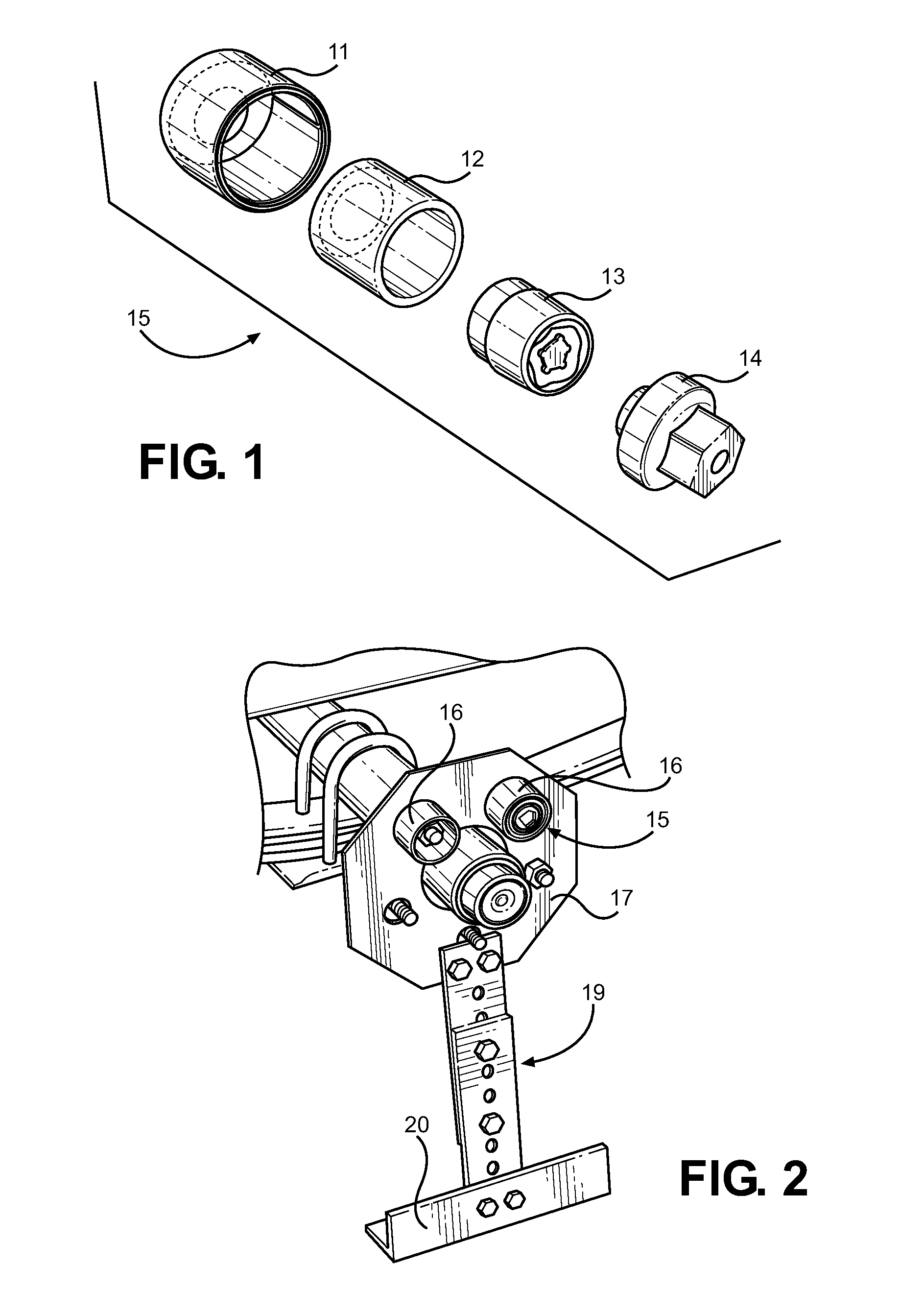
[0015]Still another object of the present invention is to provide a new and improved trailer lock that comprises four parts, including an outer cylinder, an inner cylinder, a locking lug nut and a lug nut key. The cylinders of the device are concentrically mounted and freely rotate about the shank of the locking nut. The cylinders extend over the locking nut from the wheel hub to provide a shroud therefor. The dual cylinder design defeats cutting tools, while the shroud defeats reverse thread tools from engaging the lock nut from its terminal end.

Problems solved by technology

These devices are designed to protect against wheel removal; however they do not prevent wheel rotation, and therefore afford little protection against trailer theft.
As a cutting tool engages the cylinders that surround the specialty lug key, they are free to rotate and are difficult to stabilize with secondary tools.
These devices are adapted to prevent wheel rotation; however they are easily overcome with bolt cutters, portable torches, and other cut off tools.
Because of this, a lock that completely immobilizes a wheel lug nut is needed, and one that surrounds the lock nut with a shroud that defeats many common methods of nut removal.

Method used


Image

  • Trailer Theft Deterrent Device
  • Trailer Theft Deterrent Device
  • Trailer Theft Deterrent Device

Examples


Embodiment Construction

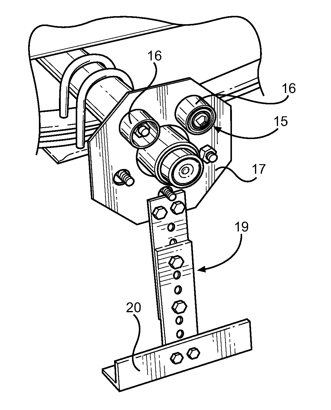
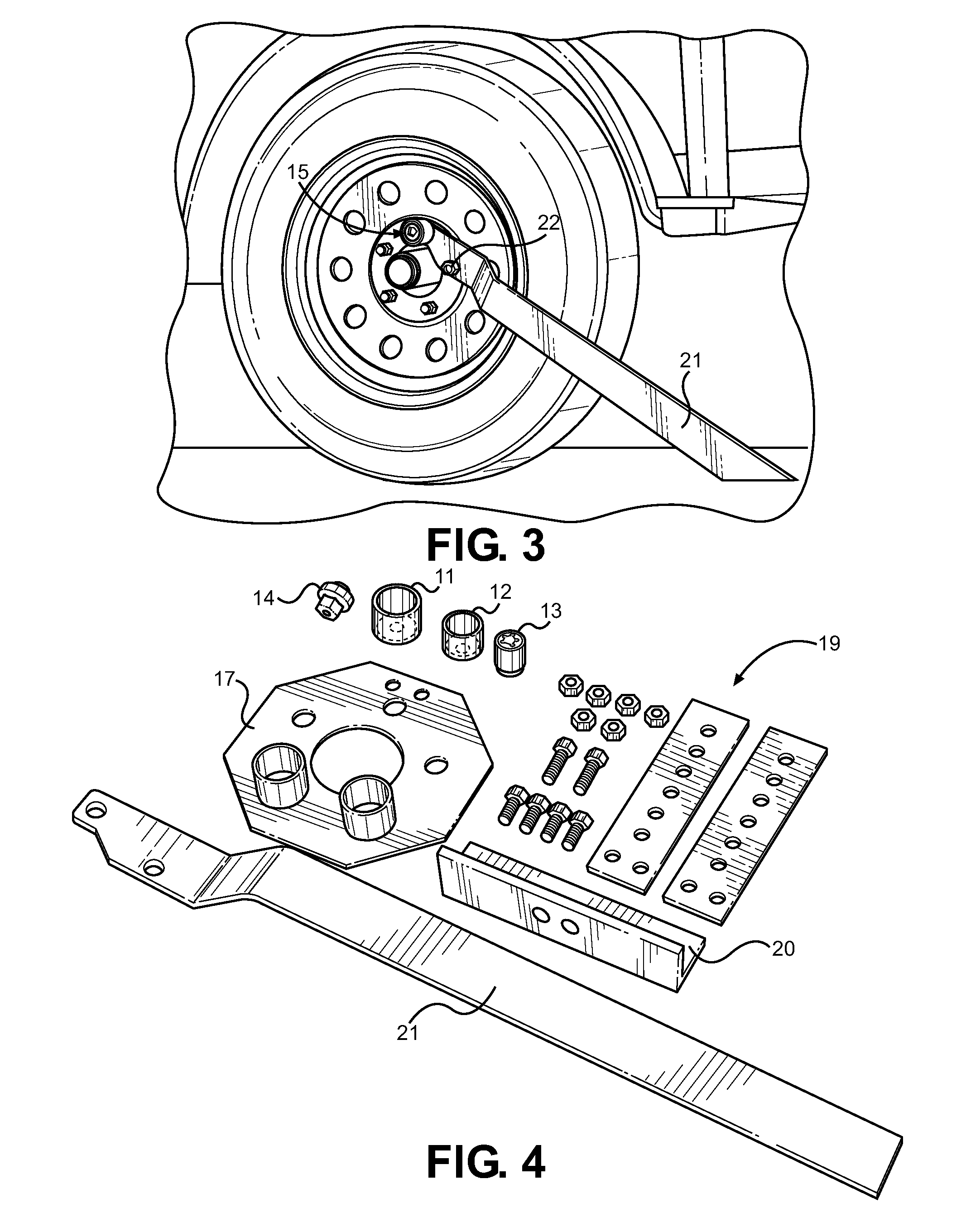
[0025]Referring now to FIG. 1, there is shown a perspective view of the preferred embodiment of the present invention, comprising an outer cylinder 11, an inner cylinder 12, a locking lug nut 13 that screws onto the lug thread, and a lock key 14. The outer cylinder 11 and inner cylinder 12 are open on end and partially closed on another end, allowing placement of the outer cylinder 11 and inner cylinder 12 over a lug thread against a wheel hub or wheel rim. The inner cylinder 12 fits inside the outer cylinder 12, and has an opening that is sized to fit the locking lug nut 13. The locking lug nut 13 comprises an interior threading to engage a vehicle lug nut, along with an outer shank that allows the inner 12 and outer 11 cylinder to rotate freely about the shank. The outer cylinder 11, the inner cylinder 12, the locking nut 13, and the locking key 14 comprise elements that form a locking assembly 15 that is adapted to securely engage a lug bolt of a vehicle.

[0026]The outer cylinder ...


PUM


Abstract

Disclosed is a security device to prevent trailer theft that attaches to the lug thread of a wheel hub to prevent wheel rotation or wheel mounting. The device includes an outer cylinder, an inner cylinder, a locking lug nut that screws onto the lug thread, and a lug nut key. The outer and inner cylinders rotate around and extend beyond the locking lug nut, utilizing a design that defeats many common methods for removing wheel locks, or requires specific tools that create considerable noise and time to defeat. An optional security bar can be engaged by removing two lug nuts to prevent wheel rotation. Also disclosed is an embodiment that prevents wheel installation on a bare wheel hub.

Description

CROSS REFERENCE TO RELATED APPLICATION[0001]This application claims the benefit of U.S. Provisional Application No. 61 / 475,049 filed on Apr. 13, 2011, entitled “Trailer Theft Deterrent.”BACKGROUND OF THE INVENTION[0002]1. Field of the Invention[0003]The present invention relates generally to the field of security devices that are attachable to trailer wheel hubs to prevent trailers from being stolen or moved. More specifically, the present invention pertains to a unique device that attaches to the lug thread of a wheel hub to prevent wheel rotation or wheel mounting.[0004]A trailer is a type of unpowered vehicle that is pulled by a powered vehicle. Some typical examples are trailers used to transport goods, boats, horses, or mobile homes. Trailers generally have two to four wheels, and attach to another vehicle by a tongue hitch. A problem inherent to the design of trailers is a lack of security means that locks them in a static position when left unattended. Trailers typically do n...

Claims


Application Information

Patent Timeline
IPC IPC(8): B60R25/00E05B65/12
CPCB60B7/16F16B39/12F16B41/005B60R25/093Y10T70/5836Y10T70/5841Y10T70/5867Y10T70/5889
Inventor JONES, CHARLES
Owner JONES CHARLES
Learn More