Optical component array having adjustable curvature

a technology of optical components and curvatures, which is applied in the field of optical component arrays, can solve the problem that curvature cannot be dynamically varied, and achieve the effects of reducing electrical resistance, facilitating image display on a monitor, and facilitating image digital storag

Active Publication Date: 2012-10-18
THE BOARD OF TRUSTEES OF THE UNIV OF ILLINOIS
View PDF4 Cites 169 Cited by
  • Summary
  • Abstract
  • Description
  • Claims
  • Application Information

AI Technical Summary

Benefits of technology

[0040]In an embodiment, any of the devices provided herein further comprise a fixture system to establish reliable electrical contact between the array of optical components on a deformable substrate and an external data acquisition system. The fixture ensures electrical contact by mechanical pressing. Cantilever springs provide mechanical pressing and contact between pin electrodes and electrodes of the optical component array, thereby establishing reliable and robust electrical contact with the array, even over large changes in substrate curvature. In an aspect, electrical resistance is reduced by polishing the surfaces of the electrode pins a

Problems solved by technology

Although effort has been devoted to ensuring electronic circuits that can stretch and bend, a challenge remains as to providing a reliable, fast and consistent means for precisely varying and

Method used


Image

  • Optical component array having adjustable curvature
  • Optical component array having adjustable curvature
  • Optical component array having adjustable curvature

Examples


example 1

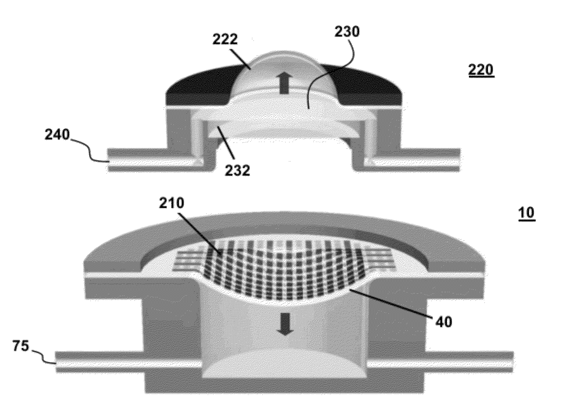
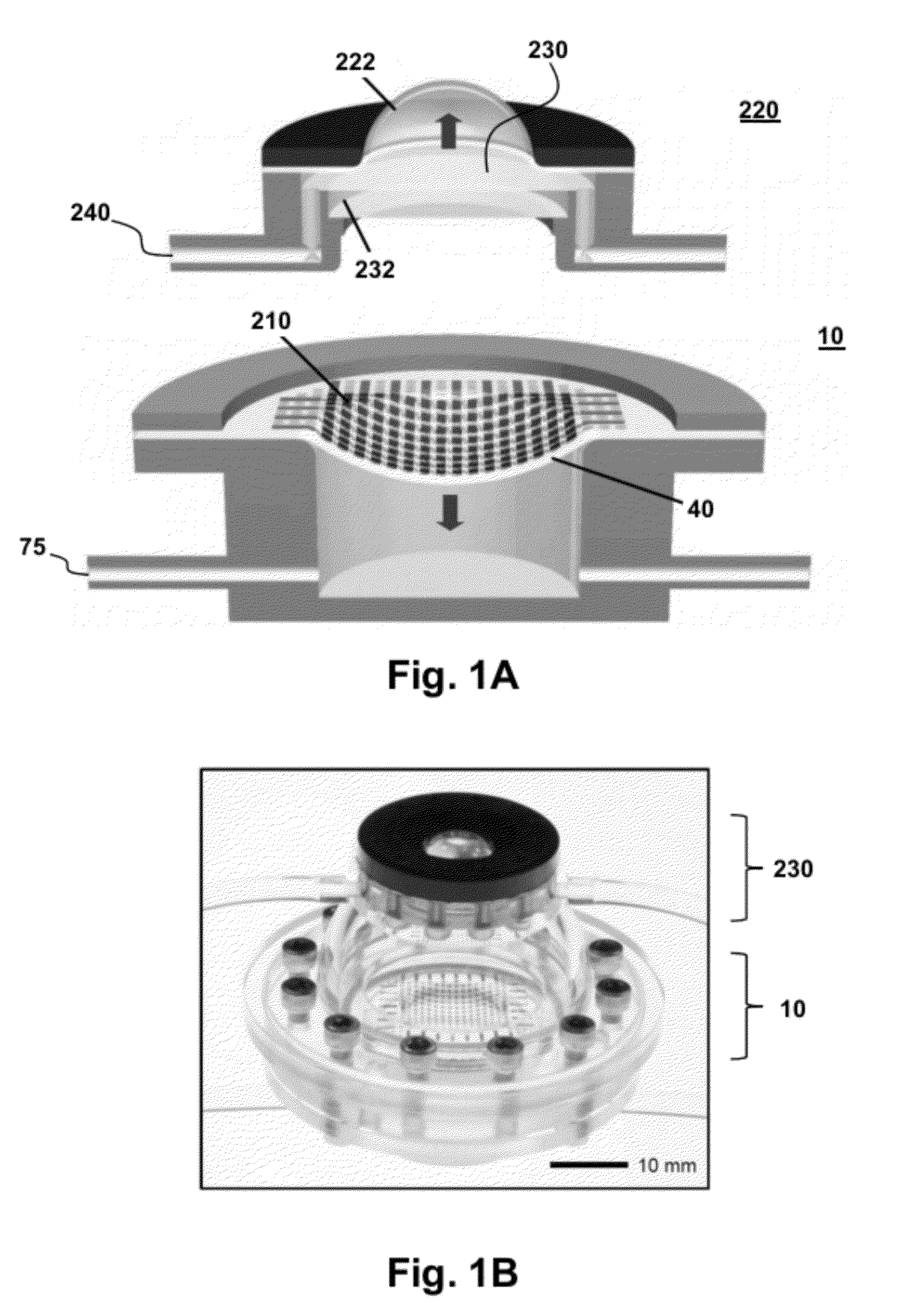
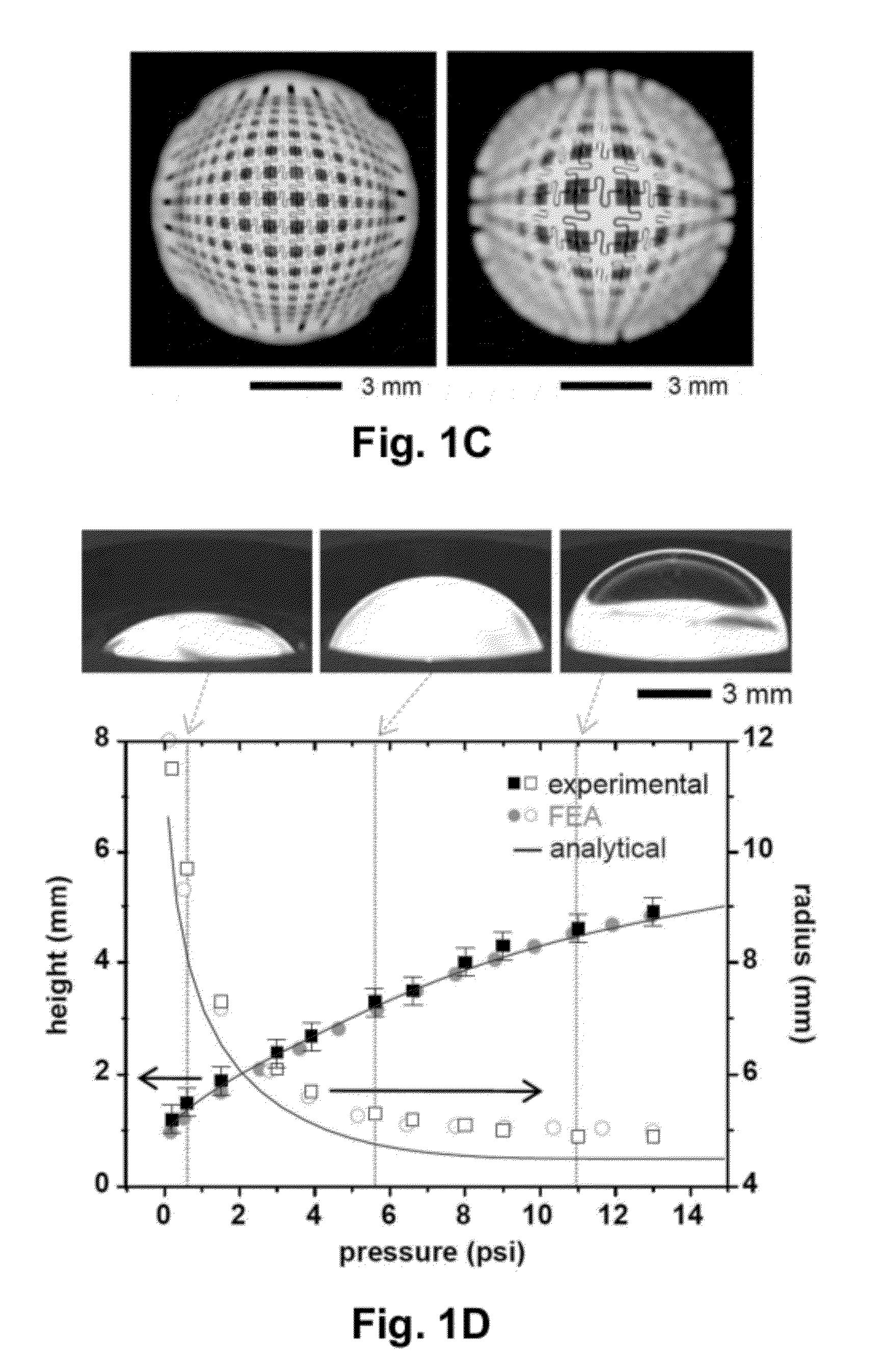
[0093]Dynamically Tunable Hemispherical Electronic Eye Camera System with Adjustable Zoom Capability. Imaging systems that exploit arrays of photodetectors in curvilinear layouts are attractive due to their ability to match the strongly non-planar image surfaces (i.e. Petzval surfaces) that form with simple lenses, thereby creating new design options. Recent work has yielded significant progress in the realization of such ‘eyeball’ cameras, including examples of fully functional silicon devices capable of collecting realistic images. Although such systems provide advantages compared to those with conventional, planar designs, their fixed detector curvature renders them incompatible with changes in the Petzval surface that accompany variable zoom achieved with simple lenses. This example describes a class of digital imaging device that overcomes this limitation, through the use of photodetector arrays on thin elastomeric membranes, capable of reversible deformation into hemispherical...

example 2

[0108]Array of optical components having adjustable curvature. This example provides information on fabricating and transferring an array of optical components, including the photodetector array of Example 1. Further discussion is provided for the pneumatic tuning system and electrical connection hardware, techniques for determining the surface geometry and pixel positions, the mechanical analysis and evaluation of the tunable lens and the imaging process.

[0109]Fabrication Process of Photodetector Array and I-V Characteristics: The steps for fabricating the photodetector array generally follow procedures previously reported(1), although the specific designs of this example are adapted to allow tunable mechanics and improved performance in the photodetectors. For the latter, the major changes are in the use of the solid source doping, both for p and n type, to replace the use of spin-on-dopants. The response of a representative individual pixel appears in the FIG. 5. Detailed fabrica...


PUM


Abstract

Provided are devices, and related methods, for controlling curvature of an array of optical components on, embedded, or partially embedded in, a deformable substrate. The array of optical components, in an aspect, comprises a deformable substrate having a contact surface and an array of mechanically interconnected optical components supported by the contact surface. An actuator is operably connected to the contact surface, wherein the actuator variably controls a curvature of said contact surface. The contact surface may have a curvature that spans concave to convex, which is tunable. In an aspect, the array of optical components is part of on optical device, such as a camera with a continuously adjustable zoom whose focus is maintained by adjusting a photodetector array curvature. In an aspect, the method is adjusting the curvature of a substrate that supports the array of optical components by applying a force to the substrate.

Description

CROSS-REFERENCE TO RELATED APPLICATIONS[0001]This application claims the benefit of priority of U.S. Provisional Patent Application No. 61 / 433,099, filed Jan. 14, 2011, which is hereby incorporated by reference in its entirety.STATEMENT REGARDING FEDERALLY SPONSORED RESEARCH OR DEVELOPMENT[0002]This invention was made with United States governmental support awarded by Defense Advanced Research Planning Agency under N66001-10-1-4008 and the National Science Foundation under ECSS-0824129. The United States Government has certain rights in the invention.BACKGROUND OF INVENTION[0003]Provided herein are arrays of optical components supported by a deformable substrate having a variable and user-controlled curvature. The devices and methods of the invention have a number of useful applications, including in the field of optical detectors, imagers and optical emitters. Methods for varying the curvature of an array of optical components and for making the disclosed devices are also provided....

Claims


Application Information

Patent Timeline
IPC IPC(8): G02B27/12H01L27/00
CPCG02B3/14G02B27/28G02B26/0875G02B26/0825
Inventor ROGERS, JOHN A.
Owner THE BOARD OF TRUSTEES OF THE UNIV OF ILLINOIS
Why Eureka
Try Eureka