
Method and device for determining leakage

a leakage detection and leakage technology, applied in the field of leakage detection, can solve the problems of inability to fully test the integrity of the refrigerating system, inability to detect extreme low refrigerant concentrations in the ppb range, and inability to integrate the test of the bubble test with the immersion test. achieve the effect of safe and fast leak detection

Active Publication Date: 2012-10-18
INFICON GMBH
View PDF35 Cites 12 Cited by
  • Summary
  • Abstract
  • Description
  • Claims
  • Application Information

AI Technical Summary

Benefits of technology

The present invention provides a method and device for detecting leaks on devices that contain gas that can be condensed. The method involves using an adsorbent to accumulate the gas and then desorbing it using heat radiation. The desorbed gas is then detected by a gas sensor, resulting in a reliable measuring result even with low gas concentrations. The method is applicable along a manufacturing line without slowing down the production cycle and can selectively measure the gas of interest while suppressing interference gases. The device includes an adsorbent and a gas sensor for selective detection of the gas.

Problems solved by technology

Here, it is a particular difficulty that extremely low refrigerant concentrations in the ppb range have to be detected within a very short time span of several 10 seconds.
A bubble test in the context of an immersion test is hardly practicable, since irreversible damage to the apparatus under test may occur.
Currently, there is no technique with which a fully functional refrigerating system could integrally be checked for refrigerant leakage in a short time span in keeping with the cycle of a manufacturing line.
This puts an extreme demand on the operator's care and attention.

Method used


Image

  • Method and device for determining leakage
  • Method and device for determining leakage

Examples


Embodiment Construction

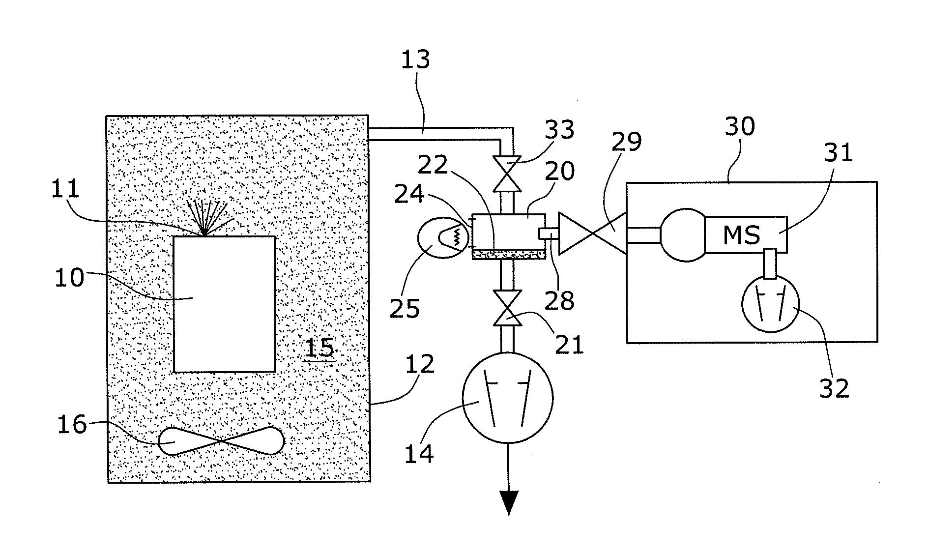
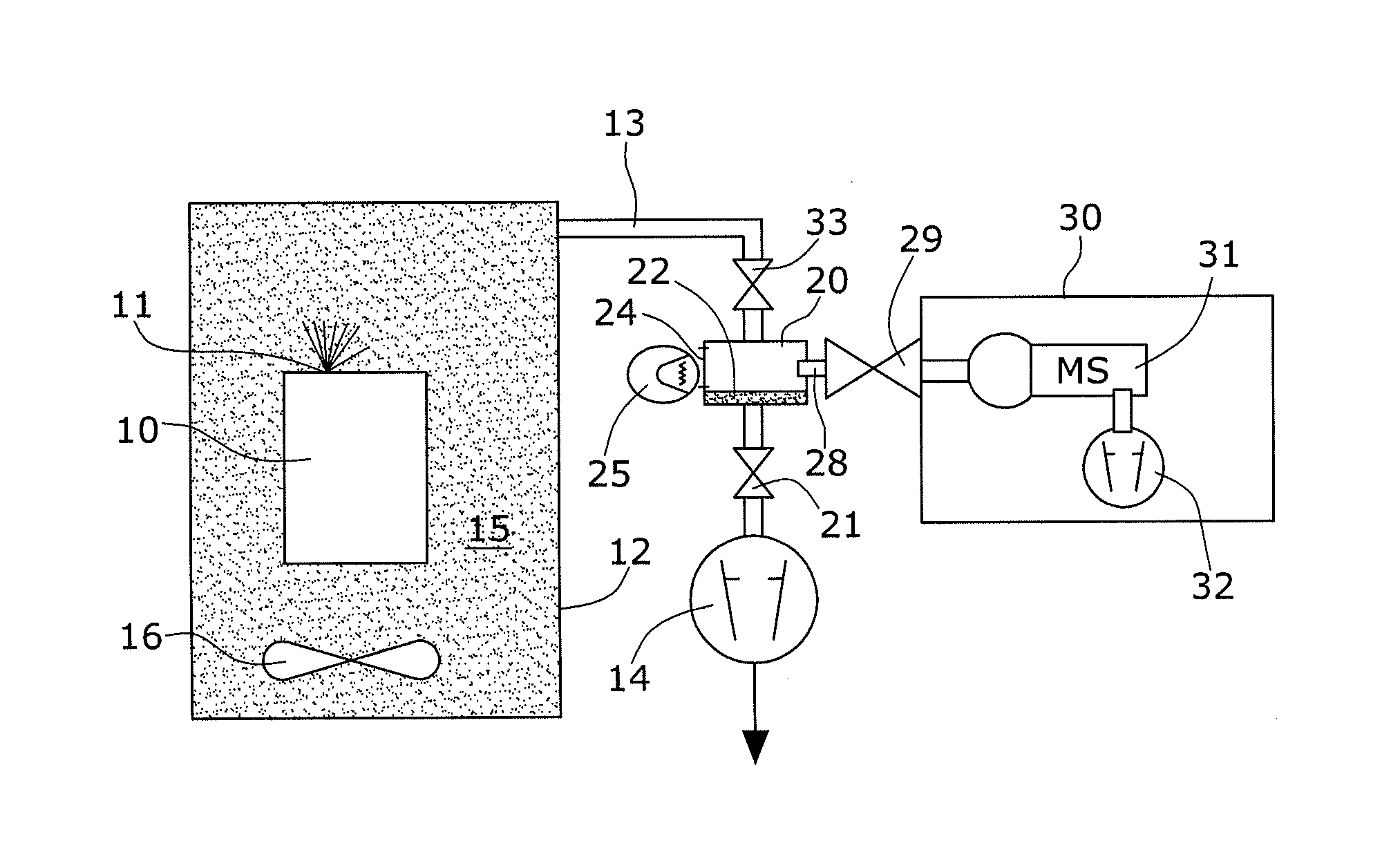
[0010]The apparatus 10 to be subject to leak detection is an apparatus comprising a refrigerant circuit. The refrigerant may be, for example, R22, R410A, R134a and the like. In any case it is a condensable gas. In FIG. 1, the apparatus 10 is represented only schematically. The refrigerant circuit of the apparatus 10 is not specifically illustrated. Refrigerant escapes at a low leakage rate from a leak 11 in the apparatus.

[0011]In the present embodiment the apparatus 10 is located in a test chamber 12 into which it has been brought for testing purposes. The tightness of the test chamber 12 is such that no substantial loss of gas occurs during the predetermined accumulation time. No pressure difference exists so that the chamber needs no vacuum properties and may be of a very simple design, thereby offering considerable cost advantages. A suction line 13 connects the chamber 12 with a delivery pump 14, drawing the ambient gas 15 around the apparatus 10 from the test chamber. The test ...


PUM

PropertyMeasurementUnit
timeaaaaaaaaaa
adsorptionaaaaaaaaaa
atmospheric pressureaaaaaaaaaa

Abstract

In order to determine leakage on a device, which contains gas that can be condensed, an adsorbent is used through which ambient gas of the object is conducted. The adsorbed gas is desorbed by means of actuating an excitation device and fed to a gas sensor containing a mass spectrometer. In this way, minute amounts of leaking gas can be determined by means of accumulation. The method is in particular suited for use in the serial production of refrigeration machines.

Description

CROSS REFERENCE TO RELATED APPLICATIONS[0001]Pursuant to 35 USC §371, this application is a National Stage of International Application No. PCT / EP2010 / 065984, filed Oct. 22, 2010, which claims priority to German Patent Application No. 102009059824.3, filed Dec. 21, 2009 under applicable paragraphs of 35 USC §119, wherein the entire contents of each above-noted document is herein incorporated by reference.TECHNICAL FIELD[0002]The invention refers to a method for leakage on a device, which contains gas that can be condensed, in particular a refrigerant, as well as to a corresponding device for determining leakage.BACKGROUND OF THE INVENTION[0003]In a series production of refrigerating systems, such as refrigerators or air conditioning systems, it is desirable to integrate a leak test at atmospheric pressure into the series production. Here, it is a particular difficulty that extremely low refrigerant concentrations in the ppb range have to be detected within a very short time span of ...

Claims


Application Information

Patent Timeline
Patent Type & Authority Applications(United States)
IPC IPC(8): G01M3/20H01J49/26G01N37/00
CPCG01M3/229G01M3/202G01M3/20G01M3/26G01M3/3281
Inventor GROSSE BLEY, WERNERKUSTER, GERHARD
Owner INFICON GMBH
Learn More