Light source unit and projector

a technology of light source and projector, which is applied in the field of light source unit and projector, can solve the problems of shortened life of excitation light source, difficult to display on screen, and inability to enhance image luminan

Active Publication Date: 2012-10-18
CASIO COMPUTER CO LTD
View PDF3 Cites 21 Cited by
  • Summary
  • Abstract
  • Description
  • Claims
  • Application Information

AI Technical Summary

Problems solved by technology

This requires excitation light to be shone continuously onto red, green and blue luminescent light emitting areas on a surface of the luminescent wheel, which requires, in turn, the excitation light source to be driven at all times, leading to a problem that the life of the excitation light source is shortened due to heat generated therein as a result of the continuous driving thereof.
In addition, due to the configuration in which the red, green and blue luminescent light rays are emitted sequentially from the corresponding luminescent light emitting areas which are formed on the luminescent wheel, it is not possible to enhance the luminance of an image by producing white light or light of a wavelength band of a highly pure complementary color through combination of the light rays of the respective colors.
Since the luminous efficiency of red, green and blue light rays which are emitted from the corresponding luminescent light emitting areas largely depends on the physical properties of the luminescent materials used, there is caused a problem that it is difficult to display on a screen an image which is superior in color balance.
In the case of this configuration being adopted, however, the luminous efficiency of a green semiconductor light emitting device is lower than those of red and blue semiconductor light emitting devices, leading to a problem that it is difficult to obtain light source light with a high luminance.

Method used


Image

  • Light source unit and projector
  • Light source unit and projector
  • Light source unit and projector

Examples


Embodiment Construction

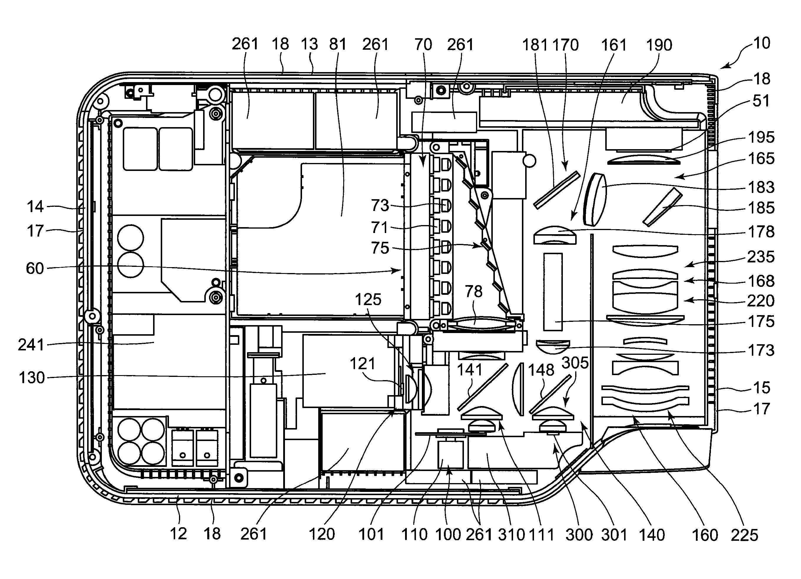
[0026]Hereinafter, a mode for carrying out the embodiment will be described. A projector 10 includes a light source unit 60, a display device 51, an light source-side optical system 170 for guiding light from the light source unit 60 to the display device 51, a projection-side optical system 220 for projecting an image emitted from the display device 51 onto a screen, and a projector control device for controlling the light source unit 60 and the display device 51.

[0027]The light source unit 60 further includes an excitation light shining device 70, a luminescent light emitting device 100 having a luminescent wheel 101 which is controlled to be driven to rotate, a red light source device 120, a blue light source device 300, and a light guiding optical system 140. The excitation light shining device 70 includes an excitation light source 71 for shining excitation light of a blue wavelength band onto the luminescent wheel 101. The luminescent wheel 101 of the luminescent light emittin...


PUM


Abstract

There is provided a light source unit comprising an excitation light shining device for emitting excitation light, a luminescent plate having a luminescent light emitting area on a base material and adapted to emit a luminescent light of a predetermined wavelength band by excitation light from the excitation shining device, two types of light source devices for emitting light of wavelength bands different from that of the light from the luminescent plate, a light guiding optical system for guiding the light from the luminescent plate and the rays from the light sources to a predetermined plane, and a light source control device for controlling the emission from the excitation light shining device and the light sources, wherein a synthetic light or a single-color light are emitted by controlling the emissions from the excitation light shining device and the light sources by the light source control device.

Description

CROSS-REFERENCE TO RELATED APPLICATIONS[0001]This is a Divisional of U.S. application Ser. No. 12 / 913,924, filed Oct. 28, 2010, which is based upon and claims the benefit of priority under 35 USC 119 of Japanese Patent Application No. 2009-247689 filed on Oct. 28, 2009, the entire contents of both of which, including the description, claims, drawings and abstract thereof, are incorporated herein by reference.BACKGROUND OF THE INVENTION[0002]1. Field of the Invention[0003]The present invention relates to a light source unit and a projector which includes the light source unit.[0004]2. Description of the Related Art[0005]Patent Document 1 (Japanese Unexamined Patent Publication No. 2004-341105), for example, proposes a light source unit having a light emitting diode which functions as an excitation light source and a luminescent wheel in which luminescent material layers are formed on a transparent base material for converting ultraviolet light emitted from the excitation light source...

Claims


Application Information

Patent Timeline
Patent Type & Authority Applications(United States)
IPC IPC(8): F21V9/16G03B21/00F21V9/40
CPCG03B21/14G03B33/08G03B21/206H04N9/3197G03B21/204H04N9/3117G03B21/2013
Inventor OGINO, HIROSHIUMAMINE, OSAMUMASUDA, HIROKIOHTA, MASANORIOGURA, NAOTSUGUSHIBASAKI, MAMORUKUROSAKI, HIDEYUKIOGAWA, MASAHIRO
Owner CASIO COMPUTER CO LTD
Why Eureka
Try Eureka