Server rack system

a server rack and rack technology, applied in the field of rack systems, can solve the problems of increasing equipment costs, ineffective improvement of heat dissipation efficiency, etc., and achieve the effects of favorable heat dissipation efficiency, not restrained fan dimensions, and improved heat dissipation efficiency

Active Publication Date: 2012-10-18
INVENTEC CORP
View PDF3 Cites 13 Cited by
  • Summary
  • Abstract
  • Description
  • Claims
  • Application Information

AI Technical Summary

Benefits of technology

[0020]To sum up, the heat-dissipating wall is pivoted to the rear end of the rack, and the fans are configured on the heat-dissipating wall according to the embodiments of the invention. The fans are not configured in the rack, and therefore the dimensions of the fans are not restrained. Namely, l

Problems solved by technology

Accordingly, only the small-sized fans can be employed, and the heat-dissipating efficiency cannot be effectively improved.
Since the small-sized fans often have less favo

Method used


Image

  • Server rack system
  • Server rack system
  • Server rack system

Examples


Embodiment Construction

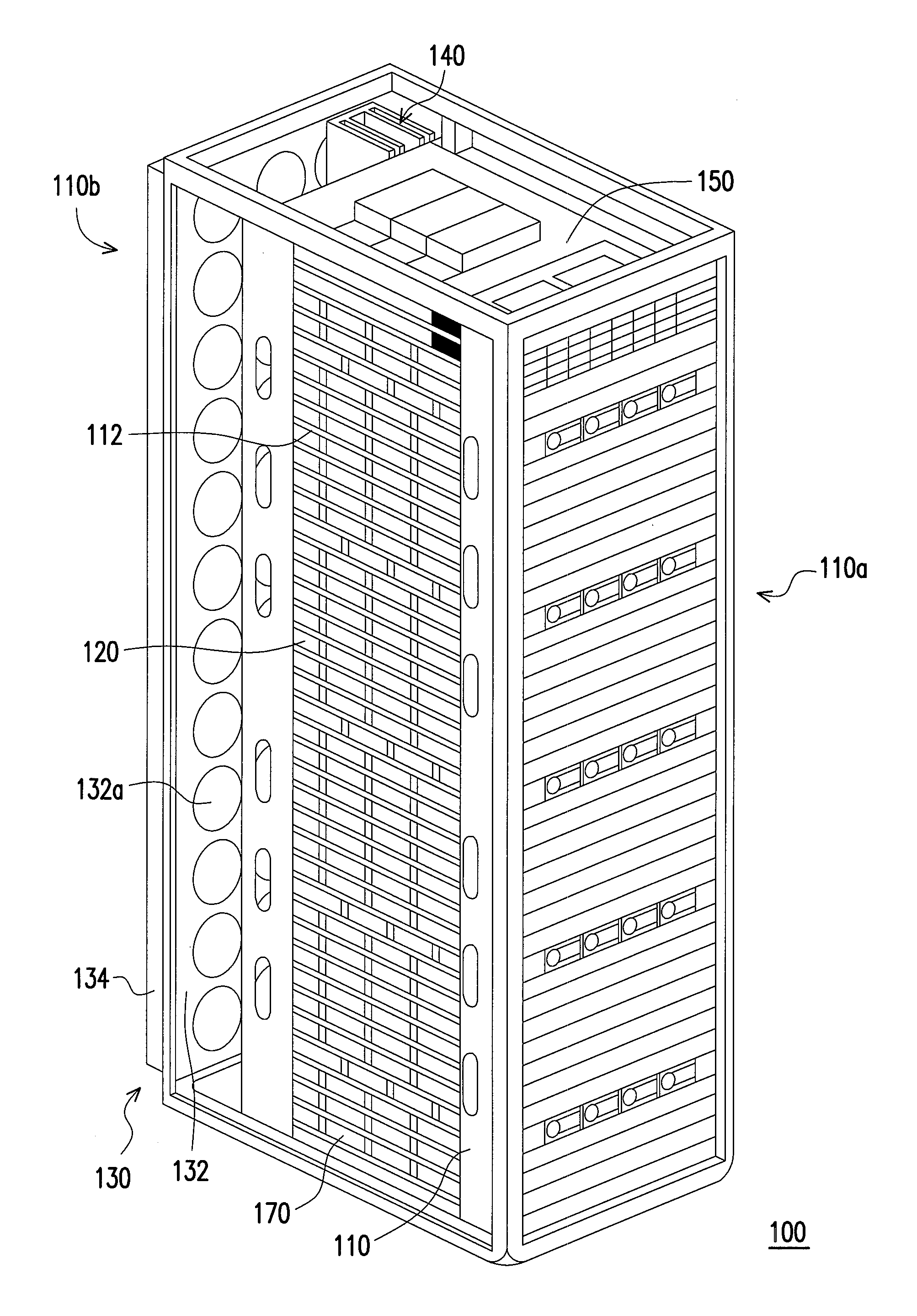
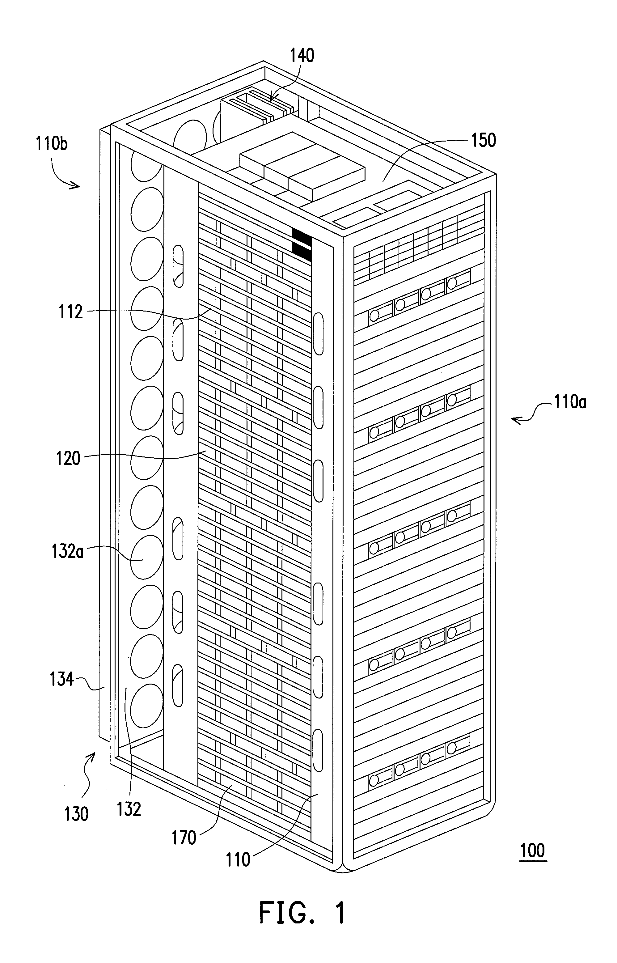
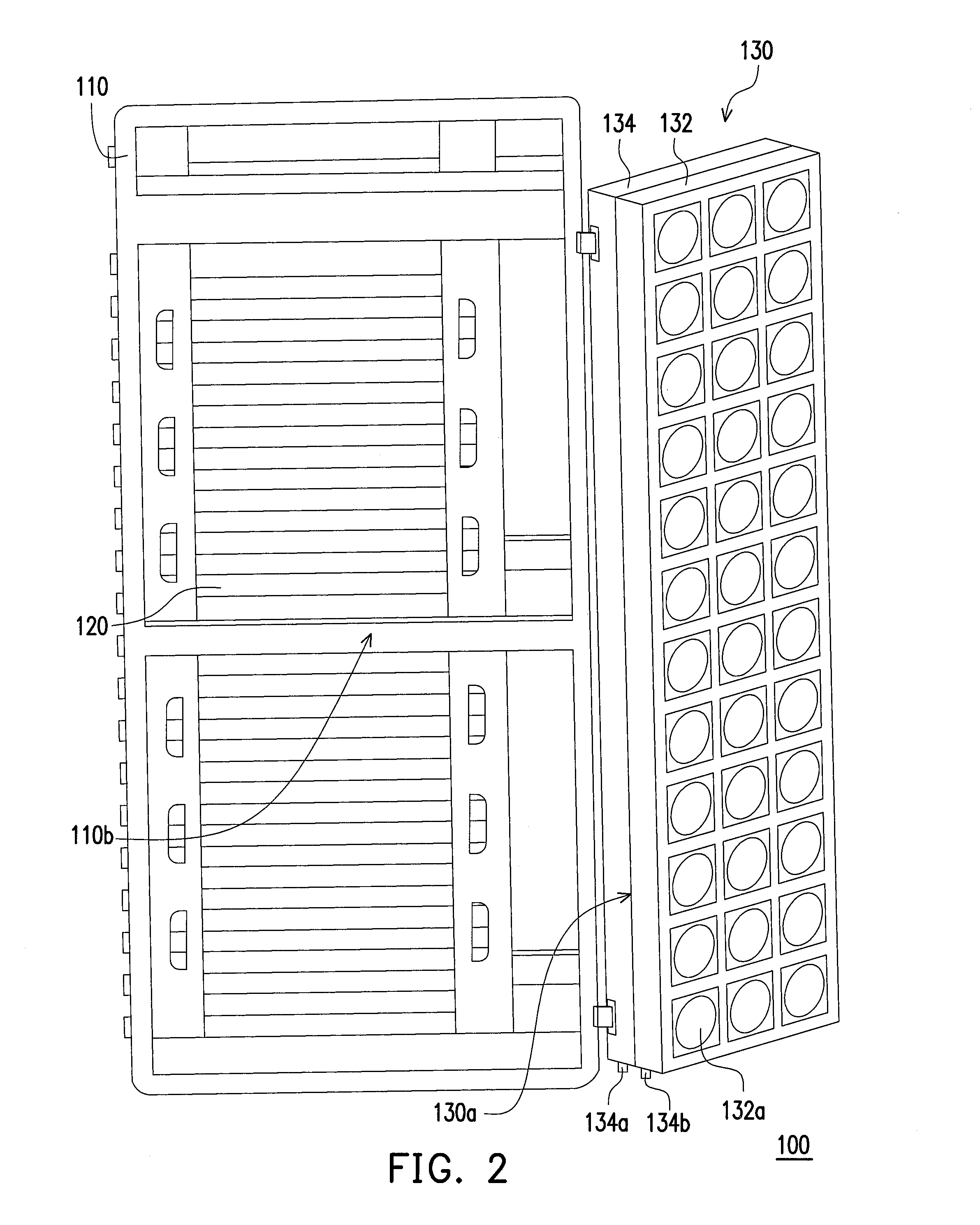
[0028]FIG. 1 is a three-dimensional view illustrating a server rack system according to an embodiment of the invention. FIG. 2 is a three-dimensional view illustrating that the heat-dissipating wall depicted in FIG. 1 is unfolded away from the rack. With reference to FIG. 1 and FIG. 2, the server rack system 100 of this embodiment includes a rack 110, a plurality of servers 120, and a heat-dissipating wall 130. The rack 110 has a plurality of guiding rails 112. Besides, the rack 110 has a front end 110a and a rear end 110b opposite to the front end 110a. The servers 120 are slidably configured on the guiding rails 112 respectively and located in the rack 110. Besides, the servers 120 are adapted for being moved into the rack 110 or moved out of the rack 110 from the front end 110a. The heat-dissipating wall 130 is pivoted to the rear end 110b and adapted for being folded against the rear end 110b or being unfolded away from the rear end 110b. The heat-dissipating wall 130 includes a...


PUM


Abstract

A server rack system includes a rack, servers, and a heat-dissipating wall. The rack has guiding rails, a front end, and a rear end opposite to the front end. The servers slidably configured on the guiding rails and in the rack are adapted for being moved into or out of the rack from the front end. The heat-dissipating wall is pivoted to the rear end and adapted for being folded against or unfolded away from the rear end. The heat-dissipating wall includes a fan wall. Fans lie on the fan wall. The fans are adapted for sucking cool air, such that the cool air enters the rack from the front end and passes through the servers. Heat exchange between the cool air and the servers is carried out to generate hot air that flows out of the rack through the heat-dissipating wall to dissipate heat of the servers.

Description

CROSS-REFERENCE TO RELATED APPLICATION[0001]This application claims the priority benefit of China application serial no. 201110097505.0, filed on Apr. 13, 2011. The entirety of the above-mentioned patent application is hereby incorporated by reference herein and made a part of this specification.BACKGROUND OF THE INVENTION[0002]1. Field of the Invention[0003]The invention relates to a rack system, and particularly relates to a server rack system.[0004]2. Description of Related Art[0005]A server is the core which serves all the computers in a network system and has the functions of providing network users with discs, printing services, and so forth. Meanwhile, the server allows the users to share the resources in the network. The basic framework of the server is approximately the same as that of an ordinary personal computer and includes a central processing unit (CPU), a memory, and input / output (I / O) equipment, which are connected by a bus inside. Through north bridge chips, the CP...

Claims


Application Information

Patent Timeline
IPC IPC(8): G06F1/20
CPCG06F1/20H05K7/20781H05K7/20736
Inventor WANG, SHI-FENGXU, JI-PENGCHENG, TSAI-KUEI
Owner INVENTEC CORP
Why Eureka
Try Eureka