
Video encoder and video decoder

a video encoder and video decoding technology, applied in the field of video encoders and video decoders, can solve the problem of encoding/decoding efficiency becoming lower depending on the application

Inactive Publication Date: 2012-10-18
FUJITSU LTD
View PDF6 Cites 18 Cited by
  • Summary
  • Abstract
  • Description
  • Claims
  • Application Information

AI Technical Summary

Benefits of technology

The invention is a video encoder that generates encoded information by predicting the signal of an encoding target and comparing it to a reference picture. The encoder selects a scan pattern that minimizes the amount of information needed to encode the prediction error signal, which is the difference between the target and the prediction signal. The video encoder can be used to encode both luminance and color difference signals, and the technical effect is to improve the efficiency and accuracy of video encoding.

Problems solved by technology

However, according to conventional techniques, the encoding / decoding efficiency becomes lower depending on characteristics of images.

Method used


Image

  • Video encoder and video decoder
  • Video encoder and video decoder
  • Video encoder and video decoder

Examples


first embodiment

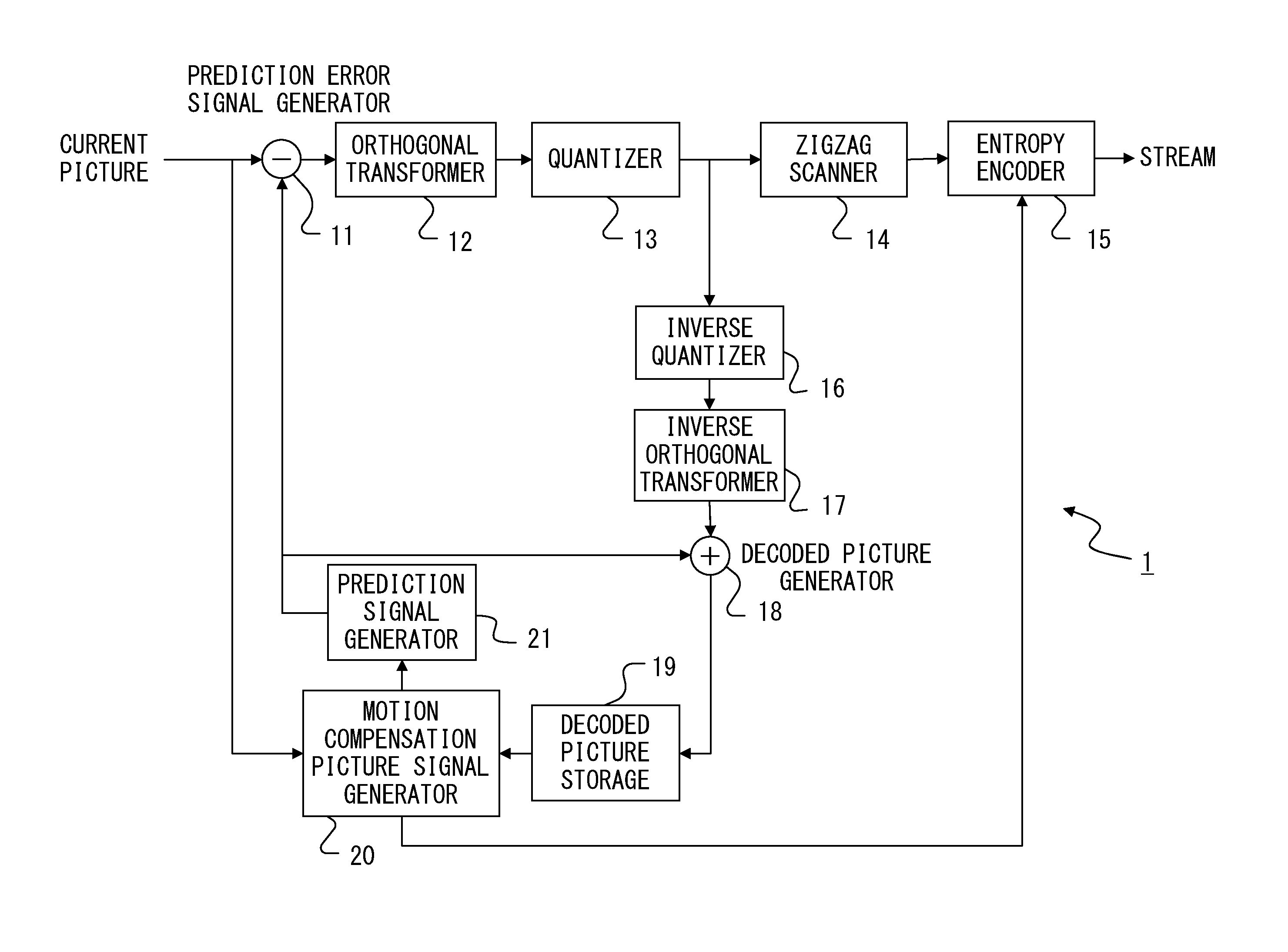
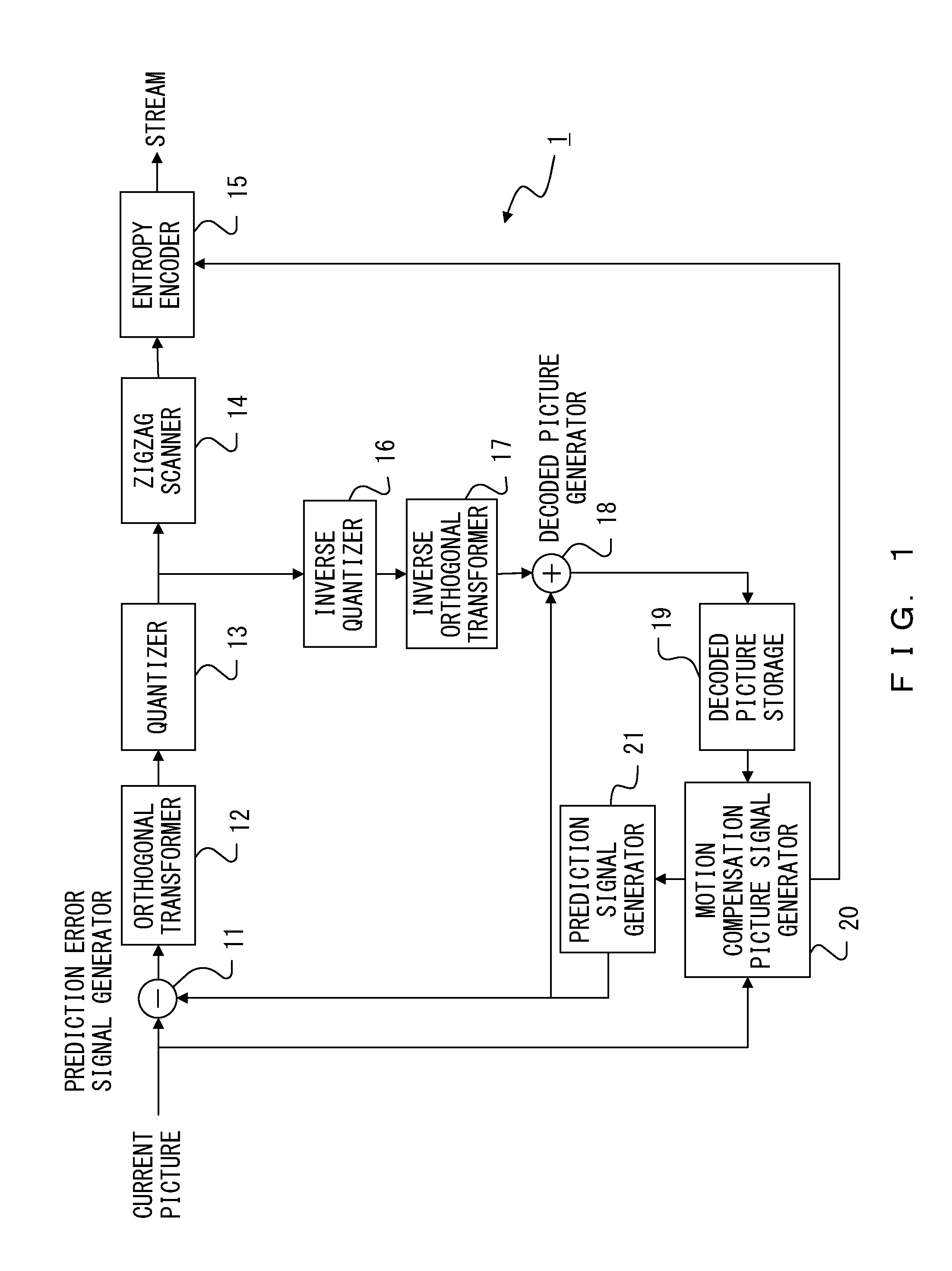
[0077]FIG. 9 illustrates a configuration of an encoder according to a first embodiment. The encoder according to the first embodiment includes the prediction error signal generator 11, the orthogonal transformer 12, the quantizer 13, the inverse quantizer 16, the inverse orthogonal transformer 17, the decoded picture generator 18, the decoded picture storage 19, the motion compensation picture signal generator 20, the prediction signal generator 21, an inter motion-compensation-signal difference signal generator 111, a selector 112, a zigzag scanner 113, and an entropy encoder 114. The prediction error signal generator 11, the orthogonal transformer 12, the quantizer 13, the inverse quantizer 16, the inverse orthogonal transformer 17, the decoded picture generator 18, the decoded picture storage 19, the motion compensation picture signal generator 20, and the prediction signal generator 21 are substantially the same as those explained by referring to FIG. 1. Also, the inter motion-c...

second embodiment

[0108]FIG. 13 illustrates a configuration of an encoder according to the second embodiment. The encoder according to the second embodiment includes the prediction error signal generator 11, the orthogonal transformer 12, the quantizer 13, the entropy encoder 15, the inverse quantizer 16, the inverse orthogonal transformer 17, the decoded picture generator 18, the decoded picture storage 19, the motion compensation picture signal generator 20, the prediction signal generator 21, an inter motion-compensation-signal difference signal generator 121, a selector 122, and a zigzag scanner 123. The prediction error signal generator 11, the orthogonal transformer 12, the quantizer 13, the entropy encoder 15, the inverse quantizer 16, the inverse orthogonal transformer 17, the decoded picture generator 18, the decoded picture storage 19, the motion compensation picture signal generator 20, and the prediction signal generator 21 are substantially the same as those explained by referring to FIG...

third embodiment

[0132]The applicants of the present patent application have found that if the prediction error of luminance information of a pixel is large, then the prediction error of color difference information of the pixel is also large when the luminance information and the color difference information included in encoding target information are encoded. This means that there are correlations between the position of a pixel with a prediction error of luminance information and the position of a pixel with a prediction error of color difference information. These correlations exist regardless of which prediction signal generation scheme is employed from among inter prediction, bi-directional inter-frame prediction, and intra prediction. Further, these correlations also exist between R components, G components, and B components of an RGB signal.

[0133]The utilization of the above correlations makes it possible to estimate the distribution of prediction errors of luminance information from the dis...


PUM


Abstract

A video encoder includes: a motion compensation picture signal generator to generate a plurality of motion compensation picture signals in accordance with an encoding target signal and a plurality of reference pictures; a prediction signal generator to generate a prediction signal of the encoding target signal by utilizing the plurality of motion compensation picture signals; a prediction error signal generator to generate a prediction error signal; a selector to select, from among a plurality of scan patterns prepared for generating encoded information from the prediction error signal, a scan pattern that is expected to minimize an information amount of an encoded state of the prediction error signal, in accordance with the plurality of motion compensation picture signals; and a zigzag scanner to generate encoded information from the prediction error signal by using the scan pattern selected by the selector.

Description

CROSS-REFERENCE TO RELATED APPLICATION[0001]This application is a continuation of an international application PCT / JP2009 / 007359, which was filed on Dec. 28, 2009.FIELD[0002]The embodiments described herein are related to an encoder, an encoding method, and an encoding program to encode video data, and also to a decoder, a decoding method, and a decoding program to decode encoded video data.BACKGROUND[0003]Video data is encoded in a highly efficient encoding scheme when it is transmitted from a transmitter device to a receiver device, when it is stored in a storage device, or in other situations. “Highly efficient encoding” is an encoding process to transform a data stream into a different data stream in order to compress the data volume.[0004]As a highly efficient encoding method for video data, an intra-picture prediction (intra prediction) encoding method is known. This encoding scheme utilizes high spatial correlation in video data. That is to say, in this encoding scheme, it is...

Claims


Application Information

Patent Timeline
Patent Type & Authority Applications(United States)
IPC IPC(8): H04N7/32H04N19/129H04N19/137H04N19/14H04N19/147H04N19/176H04N19/186H04N19/196H04N19/46H04N19/50H04N19/503H04N19/61H04N19/625H04N19/70H04N19/93
CPCH04N19/176H04N19/46H04N19/129H04N19/61H04N19/14H04N19/577H04N19/186H04N19/146H04N19/436H04N19/93H04N19/137
Inventor MIYOSHI, HIDENOBUNAKAGAWA, AKIRA
Owner FUJITSU LTD
Learn More