Intracellular Molecular Delivery Based On Nanostructure Injectors

a nano-structure, intracellular technology, applied in the field of microinjection for introducing a substance, can solve the problems of damage effect, cell types are usually limited to larger cells with tough membranes, etc., and achieve the effect of high affinity

Inactive Publication Date: 2012-10-18
RGT UNIV OF CALIFORNIA
View PDF3 Cites 17 Cited by
  • Summary
  • Abstract
  • Description
  • Claims
  • Application Information

AI Technical Summary

Benefits of technology

[0018]An important aspect of the present invention is the use of a chemical linker, which links the biological molecule to the nanotube so that it is released into the cell, preferably in multiple copies. In a preferred form, the linker is of the formula Ar—R—X—Y where Ar is an aryl compound, R is an alkyl linker, X is a cleavable functionality; and Y is an alkyl-linked binding group for binding to a biological molecule. Ar is a polycyclic aromatic hydrocarbon, such as anthracene, naphthalene or pyrene, for being adsorbed onto a carbon surface. R—X—Y represents an alkyl (as may be substituted or modified) containing a cleavable linkage X. A preferred cleavable linkage is the disulfide bond, —S—S—. An electrostatic linker may be used, which also is cleavable within the cell, by reversing polarity on a charged tip, which is attached to the nanostructure, and by taking advantage of the naturally occurring negative charge that exists in many cells.
[0019]The capability of the nanoinjector was demon

Problems solved by technology

Microinjection, however, has several intrinsic limitations and drawbacks: i) There is a damaging effect produced by the introduction of the micropipett

Method used


Image

  • Intracellular Molecular Delivery Based On Nanostructure Injectors
  • Intracellular Molecular Delivery Based On Nanostructure Injectors
  • Intracellular Molecular Delivery Based On Nanostructure Injectors

Examples


example 1

Construction of A Nanomanipulation System

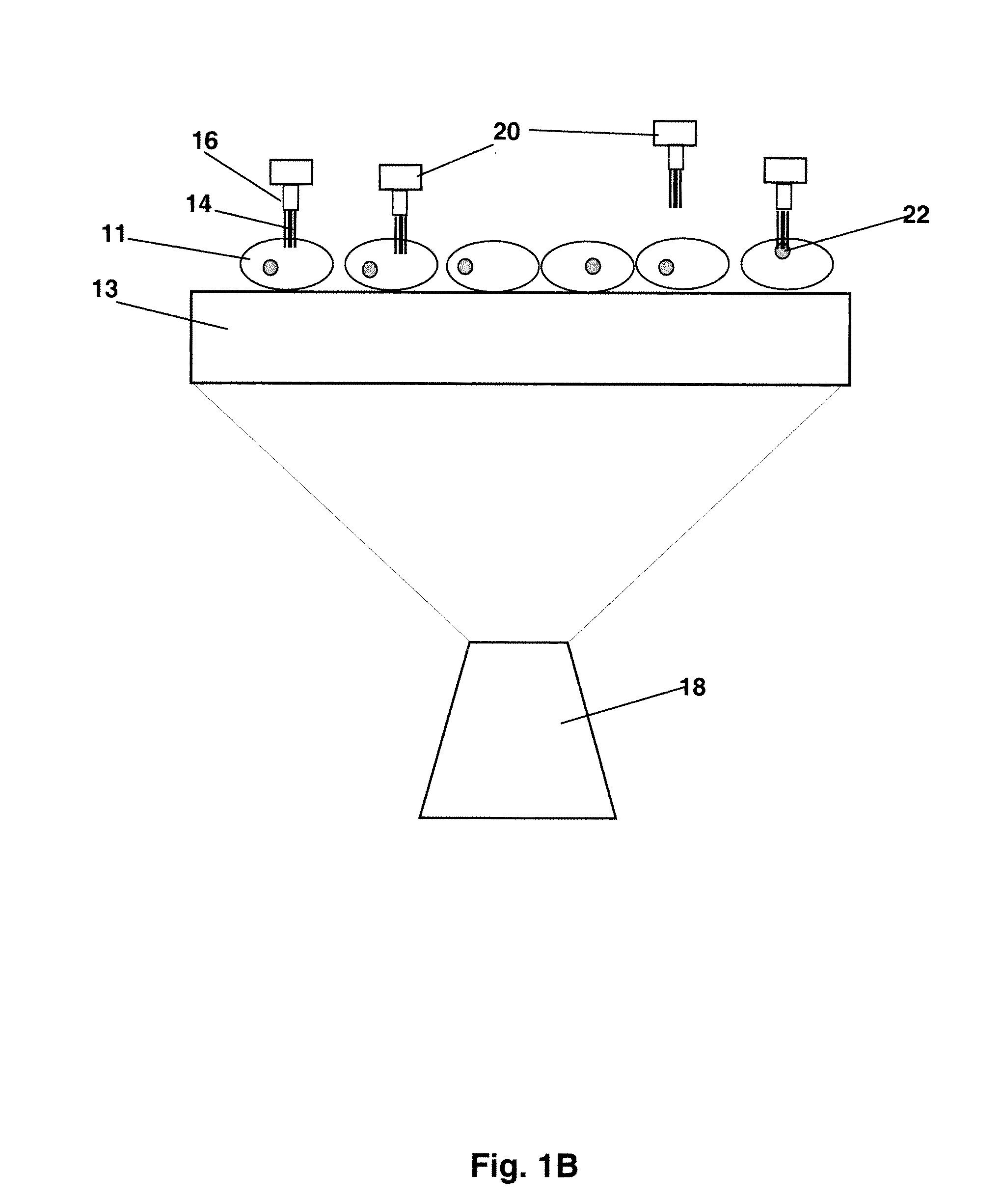
[0085]The nanomanipulation system (XYZ manipulator with imaging) was built based on a commercially available AFM (MFP-3D-BIO™, Asylum Research, Santa Barbara, Calif.) that integrates an inverted fluorescence microscope (Nikon TE2000). Recent biological applications of atomic force microscopy (14) have provided information on the integrity and local mechanical properties of cell membranes (4, 15-17). The spatial control mechanism of AFM piezo devices ensures the control of nanoneedle displacement at nanometer scale resolution. The sensitivity and ability to apply and monitor forces on a cell makes the AFM perfect nanomanipulator for penetration and withdraw of nanoneedles in this cell nanoinjection system (FIGS. 1B and C). The fabrication of CNT-AFM tips was carried out in an FEI Sirion XL 30 SEM, equipped with a homemade manipulator. The procedure was described in detail in a previous publication [Nanotechnology 16, 2493 (2005)].

[0086]In brie...

example 2

Attaching Nanoinjector To Microscopic Tip

[0087]To manipulate CNT nanoneedles, we first attached them at one end to AFM tips. Several methods have been reported for attaching CNTs to AFM tips (18-20). The CNT-AFM tips used in this work were fabricated as described previously (20). In brief, an individual MWCNT was retrieved from a metal foil by the AFM tip using a nanomanipulator inside a scanning electron microscope (SEM). As described in Ref. 20, multiwalled CNTs were prepared by the standard arc-discharge technique. After purification, a 10 μl ethanol suspension of CNTs was deposited between two metallic electrodes placed on a clean glass microscope slide, separated by a 400 μm gap. CNTs were aligned on the edge of the electrodes when a 70 V-1 kHz AC signal was applied across the gap. The metallic electrode with the CNTs was then mounted inside the SEM on the nanomanipulator with the CNTs positioned perpendicular to the plane of the AFM cantilever. SEM imaging allows us to control...

example 3

Synthesis of Linker And Attachment of A Protein

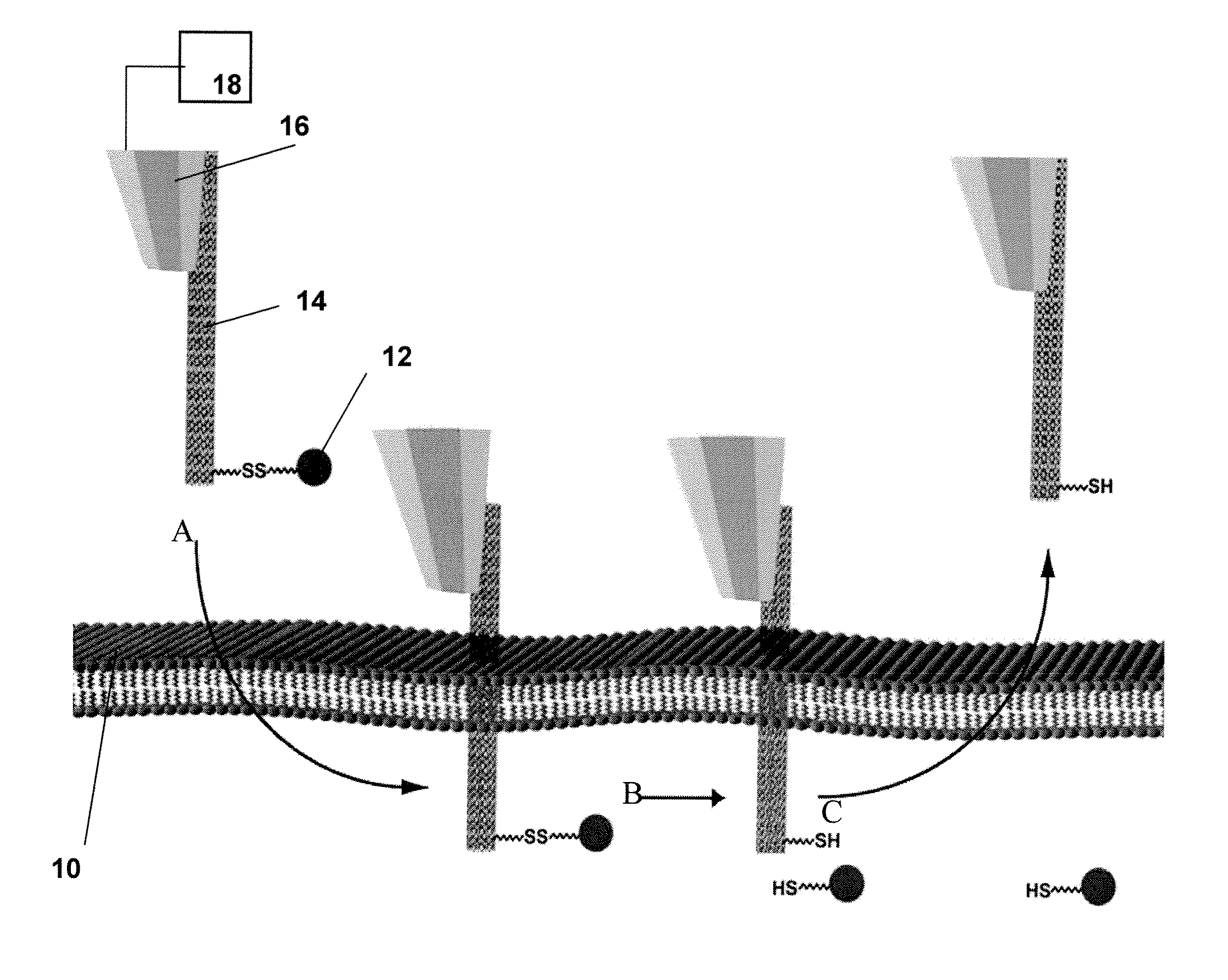
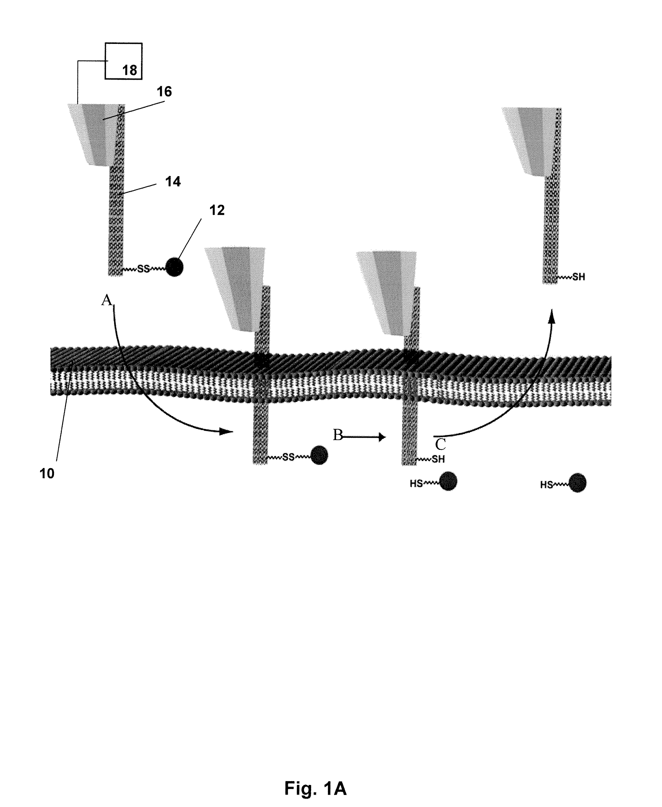
[0090]For the controlled loading and release of cargo, we aimed to design a system that would obviate the need for a carrier solvent and, accordingly, the addition of excess volume to the cell's cytosol during the injection process. Toward this end, we exploited established chemical methods for CNT surface modification and the intrinsic difference in redox potential between the intracellular and extracellular environments. Compound 1 (FIG. 3) fulfilled the functions of cargo loading and release as follows. Its pyrene moiety binds strongly to CNT surfaces via π-π stacking (12). Compound 1 is also endowed with a biotin moiety, separated from the pyrene group via a disulfide bond. In the relatively oxidizing environment of the cell's exterior, the disulfide is stable. However, once exposed to the reducing environment of the cytosol, the disulfide is cleaved, liberating attached cargo. The kinetics of disulfide bond cleavage within mammalia...


PUM

PropertyMeasurementUnit
Electric potential / voltageaaaaaaaaaa
Electrostatic forceaaaaaaaaaa

Abstract

There is disclosed a method and device for the delivery of molecules into individual cells. A device for injecting a biological molecule into a target cell comprises a microscopic tip attached to a mechanical scanning device for positioning the tip relative to the target cell and for moving the tip into the target cell; a nanostructure, such as a carbon nanotube, fixed on an end of the microscopic tip; and a biological molecule attached to the nanotube by a cleavable electrostatic or chemical linker linking the biomolecule to the nanotube, said chemical linker having a chemical linkage which is cleaved in an intracellular environment. The biological molecule may be one or more of proteins, nucleic acids, small molecule drugs, and optical labels, and combinations thereof. Exemplified are multiple walled carbon nanotubes to which a polycyclic aromatic compound is adsorbed, the aromatic compound having a side chain containing a cleavable disulfide linkage and a biotin functionality for coupling to a streptavidin-linked payload.

Description

CROSS-REFERENCE TO RELATED APPLICATIONS[0001]This application claims priority to U.S. Provisional Patent Application 60 / 878,924, filed Jan. 5, 2007, hereby incorporated by reference in its entirety.STATEMENT OF GOVERNMENTAL SUPPORT[0002]This invention was made with U.S. Government support under Contract Number DEACO2-05CH11231 between the U.S. Department of Energy and The Regents of the University of California for the management and operation of the Lawrence Berkeley National Laboratory. The U.S. Government has certain rights in this invention.REFERENCE TO SEQUENCE LISTING, COMPUTER PROGRAM, OR COMPACT DISK[0003]None.BACKGROUND OF THE INVENTION[0004]1. Field of the Invention[0005]The present invention relates to the field of microinjection for introducing a substance, particularly peptides, nucleic acids, or other biologically active molecules into biological cells, as well as cell compartments such as plastids, cell nuclei, etc., as well as to an apparatus for performing this proc...

Claims


Application Information

Patent Timeline
IPC IPC(8): C12M1/34C12N5/07C12N15/89C12Q1/02C12Q1/70B82Y5/00
CPCC12M35/00
Inventor CHEN, XINGBERTOZZI, CAROLYN R.ZETTL, ALEXANDER K.
Owner RGT UNIV OF CALIFORNIA
Why Eureka
Try Eureka