Method for reliably operating a sensor

a sensor and reliably technology, applied in the field of reliably operating a sensor, to achieve the effect of reducing resources and high reliability

Active Publication Date: 2012-10-18
IBM CORP
View PDF8 Cites 20 Cited by
  • Summary
  • Abstract
  • Description
  • Claims
  • Application Information

AI Technical Summary

Benefits of technology

[0006]It is therefore an object of the invention to provide a method, a computer-readable medium containing a set of instructions that causes a computer to perform the method, a computer program product comprising a computer-usable medium including computer-usable program code, wherein the computer-usable program code is adapted to execute the method and a system for operating at least one sensor being connected to a central control unit, which allows to monitor the at least one sensor with a high reliability and which requires reduced resources in the central control unit.
[0012]According to one embodiment of the present invention, the step of verifying correct behavior of each sensor comprises polling each sensor to transmit its sensor value to the central control unit and verifying if the sensor value lies within the sensor value range. Polling the sensor is performed in addition to the interrupt handling. Polling a sensor enables a verification of a sensor behavior. The sensor value is compared by the control unit to the sensor value range independently from generated interrupts. The upper and lower threshold forming the sensor value range can be stored in the central control unit, so that these values can be easily accessed for comparing the transmitted sensor value to the sensor value range. In one embodiment, the upper and lower thresholds are stored in the sensor and transmitted from the sensor to the control unit for performing this comparison.
[0017]In a modified embodiment of the present invention, the calculating a modified sensor value range comprises shifting the sensor value range. The width of the sensor value range is not modified, so that the modification of the sensor value range can be easily performed. The sensor value range is shifted in the direction of the sensor value causing the interrupt.
[0018]In one embodiment of the present invention, the calculating a modified sensor value range comprises defining the sensor value causing the interrupt plus an upper offset as upper threshold and defining the sensor value causing the interrupt reduced by a lower offset as lower threshold. The offset can be a static value, or can be dynamically adapted, e.g. when the sensor value reaches critical values. The calculation of the modified sensor value range can be easily implemented based on the current sensor value.
[0019]In another embodiment of the present invention, the offset for the two thresholds is chosen to be different. This allows calculating an asymmetric sensor value range based on the sensor value causing the interrupt, so that e.g. sensor values further outside the initial sensor value range can more rapidly cause a further interrupt to the central control unit. Also, in case of the sensor value approaching a critical limit or a limit depending on the sensor capabilities, an asymmetric sensor value range can be helpful, either to monitor if the sensor value further approaches the critical limit or the distance to the critical limit increases.

Problems solved by technology

Two major reasons for sensor failure comprise malfunction of a sensor itself or malfunction in a signal path between the sensor and the central control unit.

Method used


Image

  • Method for reliably operating a sensor
  • Method for reliably operating a sensor
  • Method for reliably operating a sensor

Examples


Embodiment Construction

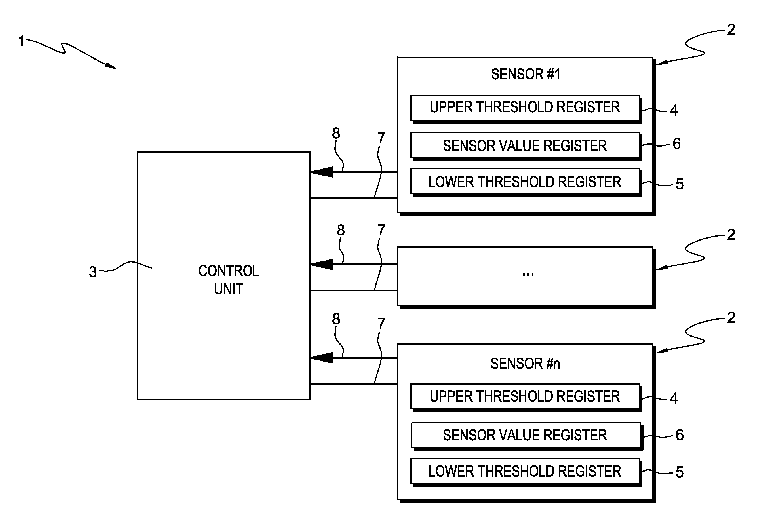
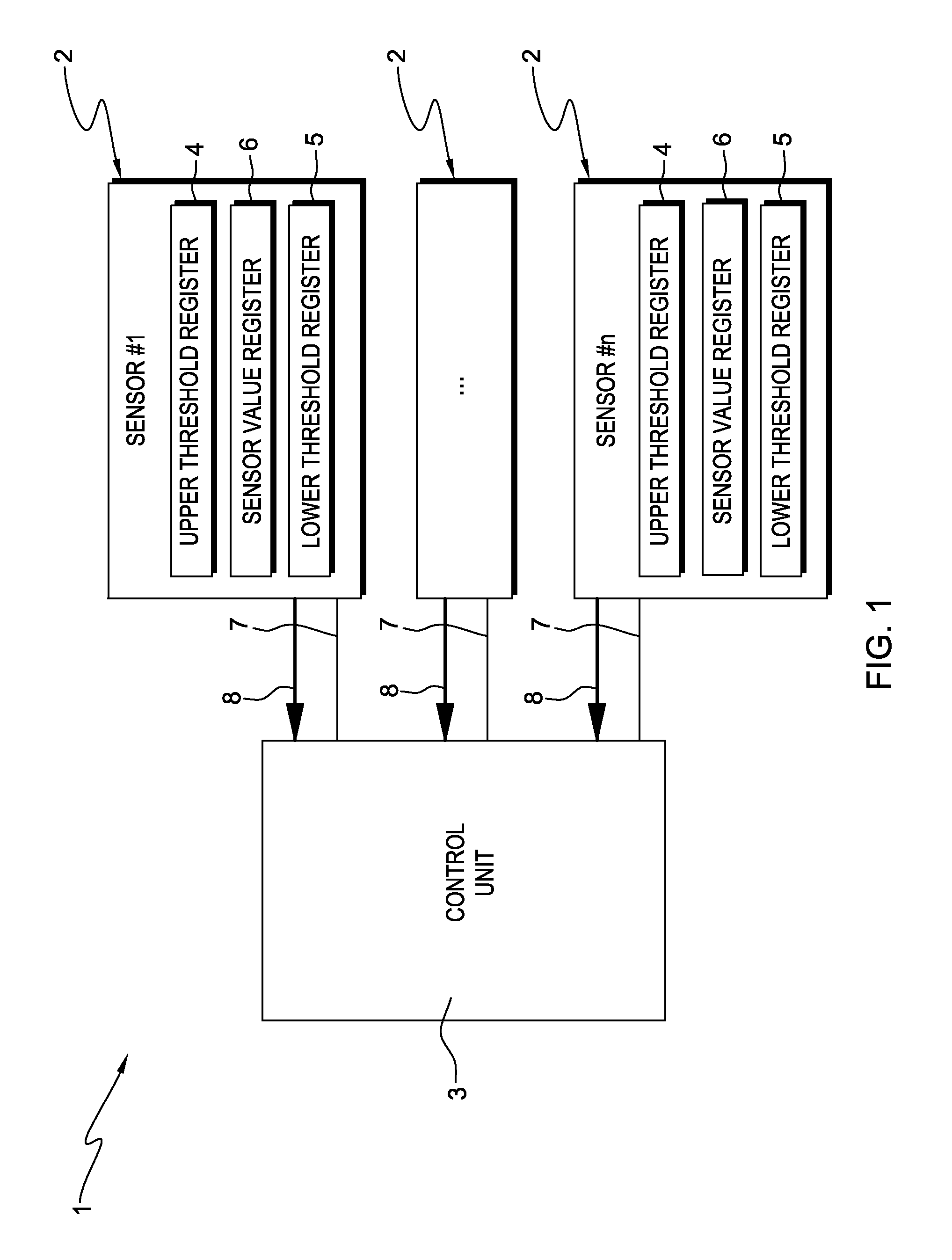
[0032]Referring to FIG. 1, a system 1 comprising multiple sensors 2 and a central control unit 3 is shown. In this example, a number of n sensors is provided, each comprising three registers, i.e. an upper threshold register 4, a lower threshold register 5 and a sensor value register 6. The upper threshold register 4 contains an upper threshold, whereas the lower threshold register 5 contains a lower threshold, the upper and the lower threshold defining a sensor value range lying between the upper and the lower threshold. The sensor value register 6 contains a current sensor value and is updated according to an implementation of the sensor 2, e.g. continuously or in pre-defined time intervals. Each sensor 2 is connected to the central control unit 3 by means of a data line 7, which enables the central control unit 3 to read and write the upper and the lower threshold registers 4, 5, and to read the sensor value register 6. Accordingly, the data line 7 is a bidirectional data line 7....


PUM


Abstract

A method is presented for reliably operating at least one sensor connected to a central control unit. Each sensor senses a sensor value for its sensor parameter and creates an interrupt to the control unit when its sensor value is outside a sensor value range limited by an upper and a lower threshold. Upon generation of an interrupt by a sensor, a modified sensor value range is calculated so that the sensor value causing the interrupt lies within the modified sensor value range, and the modified sensor value range is applied to the respective sensor. The method further includes repeatedly verifying correct behavior of each sensor. A computer-readable medium, a computer program product, and a system for executing the above-summarized method are also presented.

Description

PRIOR FOREIGN APPLICATION[0001]This application claims priority from European patent application number EP11162052.2, filed Apr. 12, 2011, which is hereby incorporated herein by reference in its entirety.FIELD OF THE INVENTION[0002]The present invention relates to a method for reliably operating at least one sensor connected to a central control unit, whereby each sensor senses a sensor value for its sensor parameter and creates an interrupt to the control unit when its sensor value is outside a sensor value range limited by an upper and a lower threshold, upon generation of an interrupt by a sensor, a modified sensor value range is calculated so that the sensor value causing the interrupt lies within the modified sensor value range, and the modified sensor value range is applied to the respective sensor. The present invention further relates to a computer readable medium, a computer program product and a system for executing the above method.BACKGROUND[0003]Methods for operating se...

Claims


Application Information

Patent Timeline
Patent Type & Authority Applications(United States)
IPC IPC(8): G01D18/00G06F19/00
CPCG01D3/036G01D18/00G01D18/002G01D18/006G06F11/30
Inventor HESS, THOMASSCHULZ, PHILIP S.STRASSER, MARKUSWAGNER, SVENWERNER, CONSTANTIN
Owner IBM CORP
Why Eureka
Try Eureka