
Displacement Sensor with Reduced Hysteresis

Inactive Publication Date: 2012-10-25
EKCHIAN JACK A
View PDF10 Cites 11 Cited by
  • Summary
  • Abstract
  • Description
  • Claims
  • Application Information

AI Technical Summary

Benefits of technology

[0008]It is an object of the invention to reduce or eliminate the hysteresis of displacement sensors by vibrating the sensing unit.
[0009]It is another object of the invention to reduce the hysteresis of liquid filled displacement sensors by decreasing the amount of stickiness or adhesion between the liquid and at least a portion of a surface contacted by the liquid.
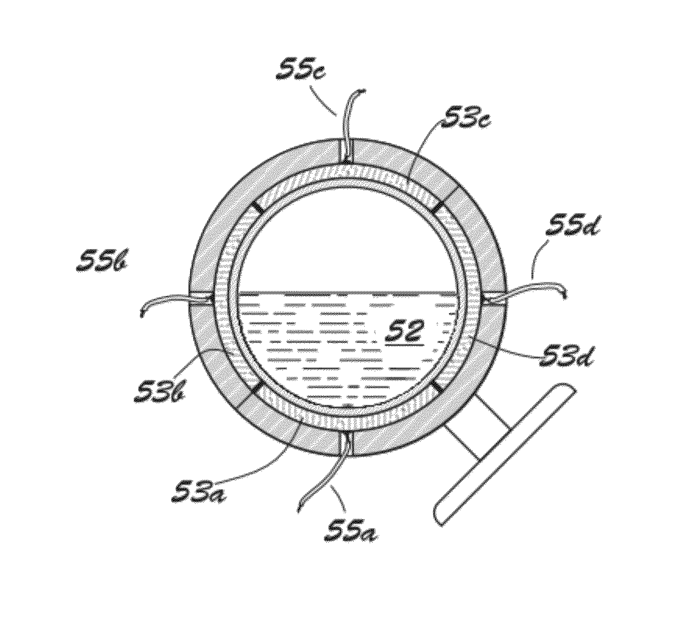
[0010]It is yet another object of the invention to reduce the hysteresis of liquid filled displacement sensors by reducing wetting by the liquid of at least a portion of a surface contacted within the vessel in which it is contained. The surface contacted by the liquid may be a part of the vessel wall or a surface otherwise enclosed within the vessel. It is preferred that the static contact angle that the liquid forms with a portion of the surface contacted by it be greater than 80°. It is more preferred that the static contact angle the liquid forms with at least a portion of the surface it contacts is greater than 90°. It is yet more preferred that the static contact angle formed between the liquid and the surface is greater than 150° and still more preferred that the static contact angle formed between the liquid and the surface is greater than 170°.
[0012]It is a still further object of this invention to reduce hysteresis of liquid filled displacement sensors by reducing the sticking or adhesion between the sensing liquid and at least a portion of the wall of the vessel where the liquid is contained by forming a gas barrier between the liquid and that portion of the surface.
[0015]In another embodiment configured according to the invention, a vessel with a liquid element comprising water is used in the sensing unit of an inclinometer. The relative position between the liquid element and the vessel is determined and used as a measure of the inclination of the sensor base. Certain materials including, for example, solids and other liquids, may be incorporated in the liquid element in the sensing unit to affect properties such as, for example, the electrical conductivity, viscosity, and surface tension of the liquid element. In order to reduce the adhesion or sticking between the liquid element and at least a portion of a surface that is contacted by it, the liquid element and / or the surface may be configured to increase the contact angle to a value greater than 100°, preferably greater than 120°, more preferably greater than 150°, and yet more preferably greater than 170°. If the liquid comprises water, this effect may be achieved by, for example, coating the surface with a hydrophobic or super-hydrophobic material or by physically or chemically modifying the micro or nano structure of the surface.

Problems solved by technology

The accuracy and effectiveness of such sensors are generally limited by their inherent hysteresis.
Generally, the accuracy of inclinometers and other displacement sensor technologies, with and without liquid sensing elements, are limited by hysteresis.
Hysteresis in such sensors is at least partially caused by stickiness or adhesion between the elements of the sensing unit that are fixed with respect to the base of the sensor and those elements that are intended to move relative to the base when the base is displaced.
In liquid filled sensors, stickiness or adhesion between the liquid element and solid surfaces that it contacts causes or contributes to the hysteresis of the sensor.

Method used


Image

  • Displacement Sensor with Reduced Hysteresis
  • Displacement Sensor with Reduced Hysteresis
  • Displacement Sensor with Reduced Hysteresis

Examples


Embodiment Construction

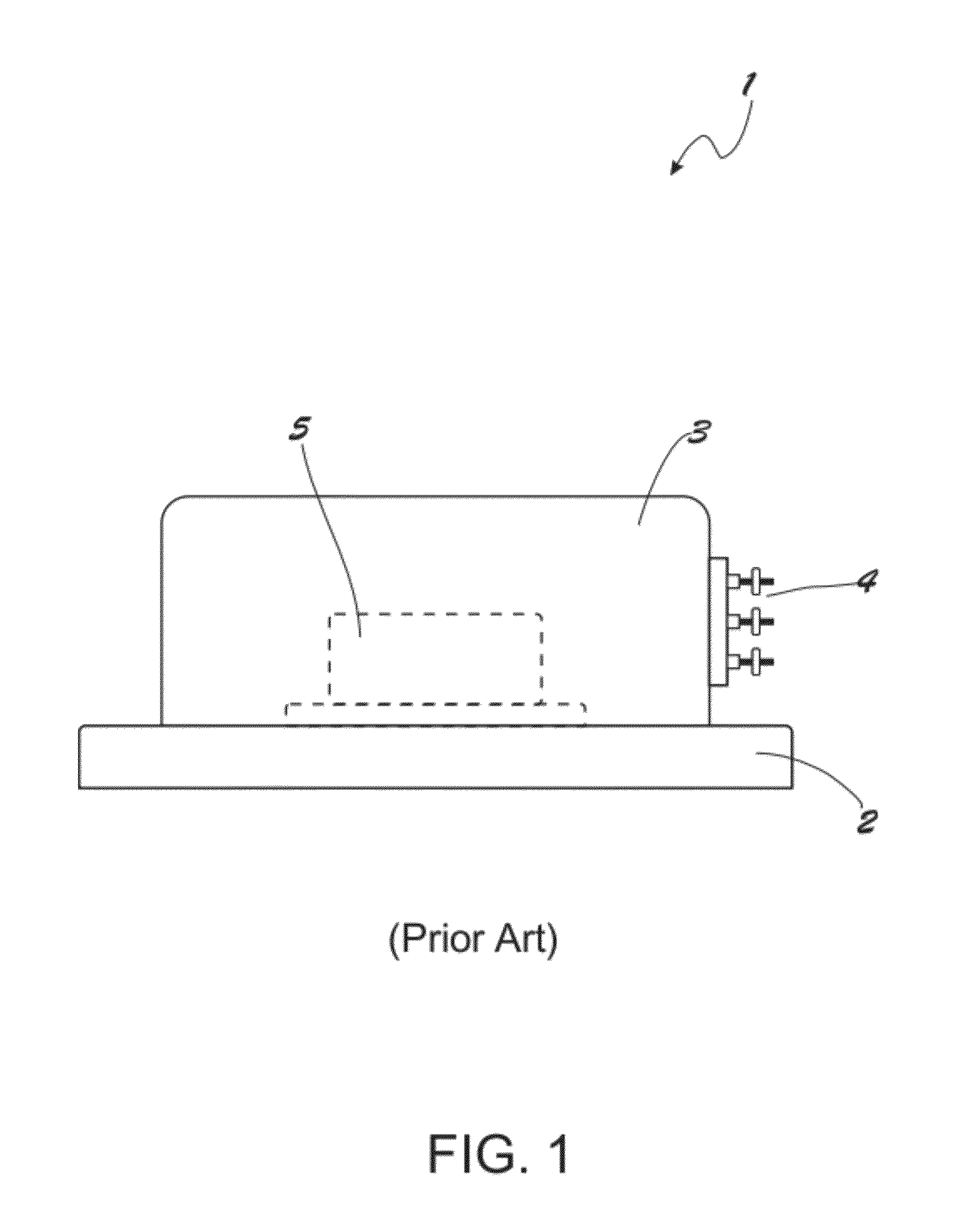
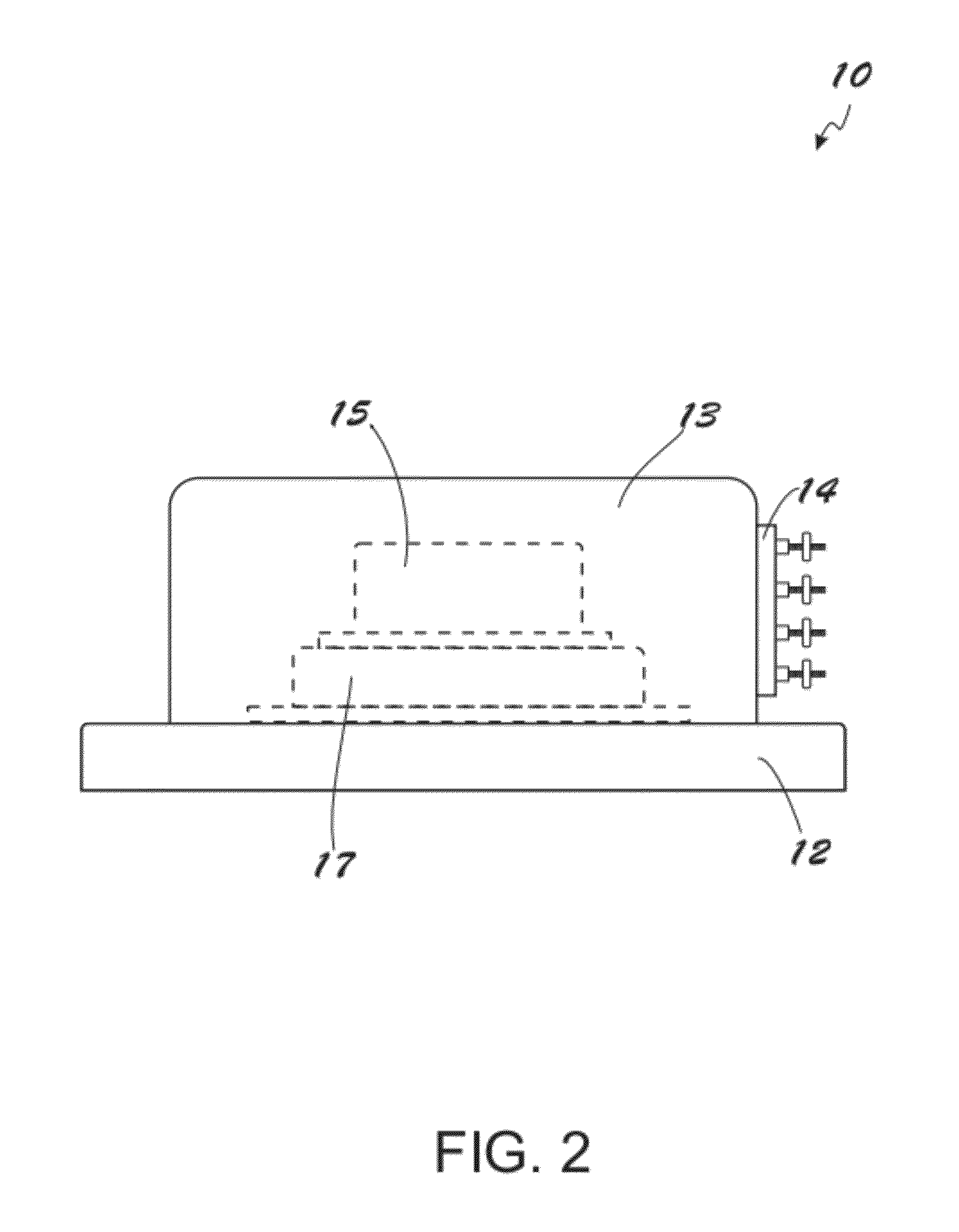
[0030]Certain exemplary embodiments will now be described to provide an overall understanding of the principles of the structure, function, manufacture and use of the system and methods disclosed herein for reducing the hysteresis of sensors or sensor components. One or more examples of these embodiments are illustrated in the accompanying drawings and described herein. Those of ordinary skill in the art will understand that the systems, methods and examples described herein and illustrated in the accompanying drawings are non-limiting exemplary embodiments and that the scope of the present invention is defined solely by the claims. The features illustrated or described in connection with one exemplary embodiment may be combined with features of other embodiments and that the features may be used individually, singularly and / or in various combinations. Such modifications are intended to be included within the scope of the present invention.

[0031]FIG. 1 shows a schematic of a convent...


PUM


Abstract

A method and apparatus are provided for reducing hysteresis in displacement sensors by reducing the resistance to motion between components in the sensing units that move relative to each other.

Description

CROSS-REFERENCE TO RELATED APPLICATIONS[0001]This application claims priority of U.S. Provisional Patent Application No. 61 / 517,597 filed Apr. 22, 2011, entitled “Improved Displacement Sensor with Reduced Hysteresis”, the contents of which are hereby incorporated herein by reference in their entirety.FIELD OF INVENTION[0002]The present invention generally relates to displacement sensors such as, for example, inclinometers, accelerometers and position transducers. More particularly, the invention relates to the reduction or elimination of hysteresis in such sensors.BACKGROUND[0003]A myriad of displacement sensors are used in industrial, commercial and residential applications. These include, for example, inclinometers and accelerometers. The accuracy and effectiveness of such sensors are generally limited by their inherent hysteresis.[0004]Displacement sensors generally comprise a base for attaching the sensor to other objects and an enclosure that is attached to the base and contain...

Claims


Application Information

Patent Timeline
IPC IPC(8): G01C9/20
CPCG01C9/20
Inventor EKCHIAN, JACK A.
Owner EKCHIAN JACK A
Learn More