Leak detection system with secure sealing mechanism

a leak detection and sealing mechanism technology, applied in the direction of measurement devices, instruments, structural/machine measurement, etc., can solve the problems of increased fuel consumption, increased drivability complications, and increased fuel consumption, and achieve the effect of increasing pressur

Active Publication Date: 2012-10-25
REDLINE DETECTION
View PDF6 Cites 6 Cited by
  • Summary
  • Abstract
  • Description
  • Claims
  • Application Information

AI Technical Summary

Benefits of technology

[0018]In use, the sealing device is interconnected to the air induction system hose or ducting in a manner identical or as near-identical as possible to which the air induction system hose or ducting is interconnected with the vehicle's air induction housing. Once so interconnected, the existing or original clamping mechanism is applied thereto allowing for the most accurate assessment as to the structural integrity of the connection and the leak detection testing conducted as per conventional methodology whereby pressurized leak detection vapor are introduced into the air induction system via a port or input formed on the sealing device. Advantageously, due to the secure interconnection between the sealing device and air induction hose or duct, substantially greater pressures can be applied to the air induction system without risk of leaks at the interface at which the test vapor are introduced which has not heretofore been available.

Problems solved by technology

To the extent leaks are present in these systems, a wide range of consequences can occur, including loss of performance, increased fuel consumption, and drivability complications.
Boosted engines also require much longer air induction ducting.
The complications from leaks in a boosted system are multiplied with the increased pressure and may have a much larger negative impact on the performance on longevity of the engine and its components.
Similarly, the ability to detect and locate leaks in the air induction systems of boosted engines has been extremely difficult for lack of an interface to introduce higher pressure vapor.
Despite the fact that such systems are well-known and extensively utilized, a significant problem still arises in the art as to how higher pressurized test gas can be delivered into the air induction system of an engine such that no pressure test vapor is lost at the interface where the test gas is introduced into the air induction system.
Indeed, maintaining the pressure at the point of entry into the air induction system is particularly important when attempting to detect leaks in turbocharged and supercharged engines that operate at substantially higher pressure, which in turn requires leak detection tests be conducted at least equal or greater pressure in order to insure adequate testing; however, substantial problems arise in simply forming a secure, leak-proof interconnection at the interface between where the pressurized gases are introduced into the air induction system to be detected.
In this respect, to the extent there is any loss whatsoever in pressure of the test vapor at the point of entry into the air induction system, the ability to detect leaks is severely diminished, especially when it is necessary or desired to test at higher pressures, however, substantial risk of pressure loss at the point of entry is exceptionally high insofar as the induction hoses and ducts of the air induction systems for each automobile manufacturer are different, and radically different designs are frequently used for each major automobile manufacturer, which can even vary significantly between the various makes and models of a particular manufacturer.
The existing device not only eliminates the ability to test critical ducting from the air filter housing to the intake piping, it also introduces additional ducting that can introduce leaks into the test.

Method used


Image

  • Leak detection system with secure sealing mechanism
  • Leak detection system with secure sealing mechanism

Examples


Embodiment Construction

[0024]The detailed description set forth below is intended as a description of the presently preferred embodiment of the invention, and is not intended to represent the only form in which the present invention may be constructed or utilized. The description sets forth the functions and sequences of steps for constructing and operating the invention. It is to be understood, however, that the same or equivalent functions and sequences may be accomplished by different embodiments and that they are also intended to be encompassed within the scope of the invention.

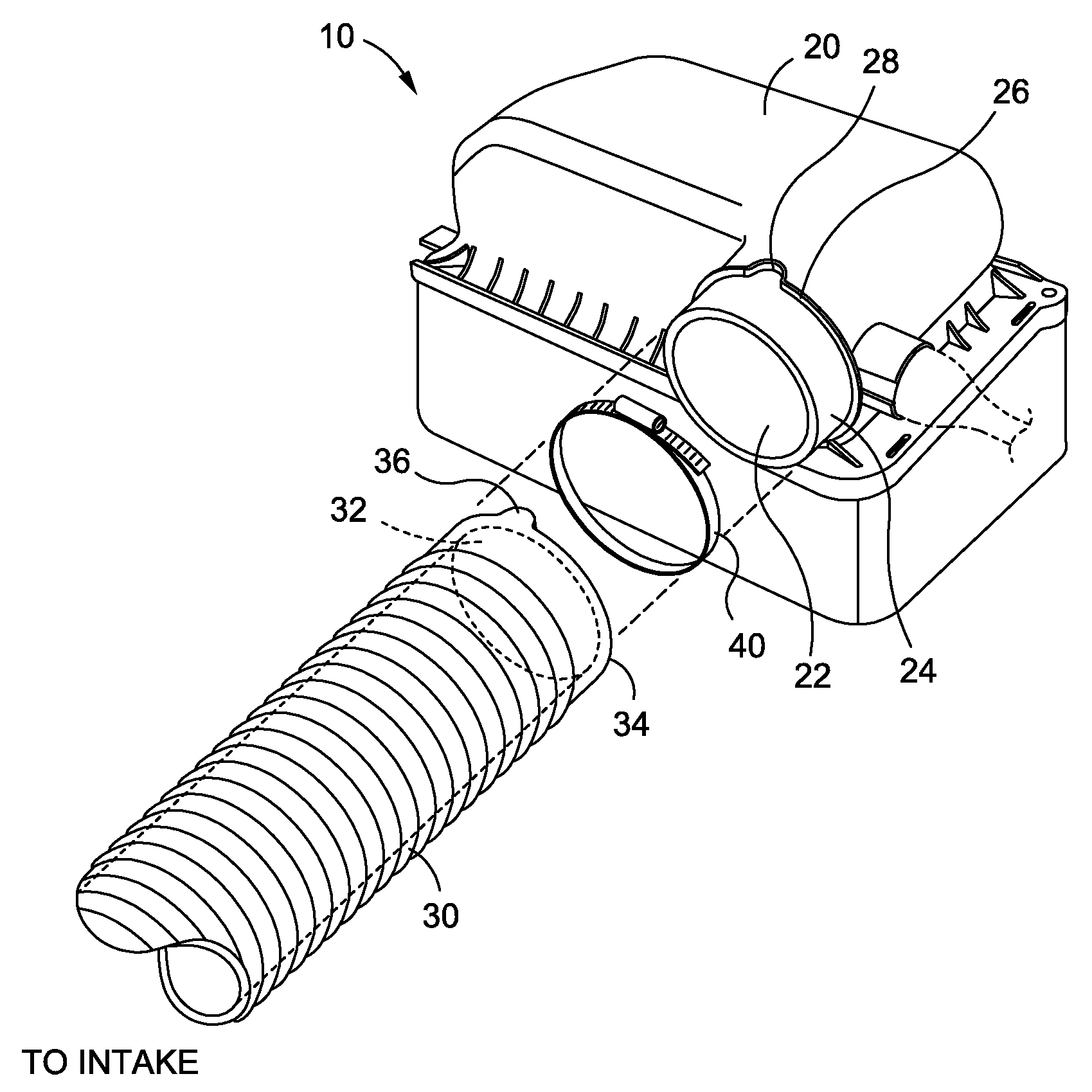
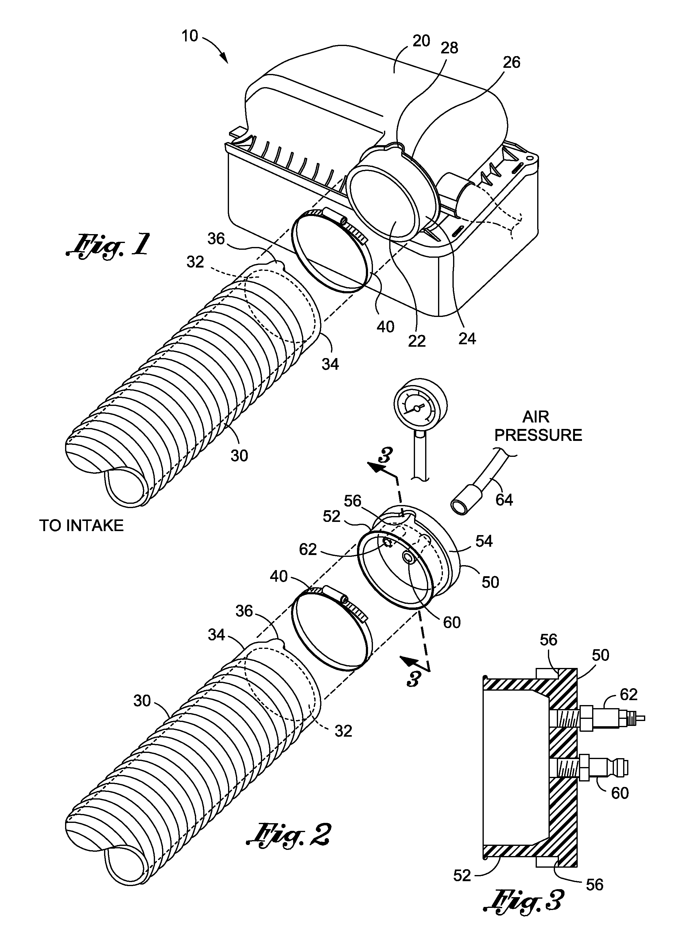
[0025]Referring now to the Figures, and initially to FIG. 1, there is shown an air induction system 10 comprising the combination of air induction system housing 20 and air induction hose 30 designed to be coupled therewith. As is well-known and per conventional air induction design, the air induction system housing 20 and air induction hose 30 are operative to regulate and assist air flow as needed for use by the vehicle's int...


PUM


Abstract

An automotive leak detection system that includes means for forming a secure, leak-proof interconnection between a source of pressurized leak detection vapor and the automobile engine's air induction system ducting or hose. The system includes a sealing mechanism that is specially contoured and configured to matingly interconnect about the opening defined about the distal-most end of the air induction system ducting or hose such that the sealing device and hose form a secure, leak-proof interconnection. The sealing device may be provided with a customized periphery that is designed to correspond and matingly engage with the footprint or specific configuration of the distal end of the air induction system ducting or hose of a specific car manufacturer and/or specific make and model air induction system ducting or system.

Description

CROSS-REFERENCE TO RELATED APPLICATIONS[0001]Not ApplicableSTATEMENT RE: FEDERALLY SPONSORED RESEARCH / DEVELOPMENT[0002]Not ApplicableBACKGROUND[0003]The present invention is directed to improve leak detection systems, and more particularly, automobile-based leak detection systems that utilize higher pressure vapor as deployed through the automobile's air induction system via a sealing mechanism that forms a secure interconnection that minimizes vapor leaks and pressure loss at the interface where such pressurized vapor is delivered to the automobile's air induction system using the automobile's own induction system ducting or hose.[0004]Systems and methods for detecting leaks in internal combustion engine systems are well-known in the art. In this regard, leak detection systems are extensively used in engine diagnostic and maintenance procedures, and in particular can be utilized to find leaks in EVAP systems, valves, gaskets, hoses, vacuum lines and reservoirs, throttle bodies, EGR...

Claims


Application Information

Patent Timeline
Patent Type & Authority Applications(United States)
IPC IPC(8): G01M3/20
CPCG01M3/22G01M3/022
Inventor PARKER, ZACHARY
Owner REDLINE DETECTION
Why Eureka
Try Eureka