Environmentally Protected Housingless Generator/Motor

a generator/motor and enclosure technology, applied in the direction of dynamo-electric machines, electrical devices, supports/enclosements/casings, etc., can solve the problems of reducing the thermal resistance from the end turn to the cup, and it is difficult to vent air out of the ecap with the caps in place, so as to achieve the protection level of an injection molded motor, the effect of minimal capital expense and minimal investmen

Active Publication Date: 2012-10-25
KOLLMORGEN CORP
View PDF18 Cites 24 Cited by
  • Summary
  • Abstract
  • Description
  • Claims
  • Application Information

AI Technical Summary

Benefits of technology

[0008]In all embodiments, the protective barriers are formed of or include waterproof, non-conductive material. One preferred material is polyphenylene sulphide. It is also possible to use a metal or metal alloy material with a plastic, epoxy, such as powder coating, or other insulator to form the protective barriers. A non-metal material avoids eddy currents produced in the material. At least one of the protective barriers advantageously includes an exit permitting passage of leads for the stator arrangement. Epoxy, which typically encases the conductive coils, can be used to at least partially secure the protective barriers to the stator. Adhesive or grease may also be used between the epoxy encapsulated coils and the protective barrier to enhance heat transfer.
[0009]In one form of the invention, the process utilized will likely include bonderizing a stack of laminations to seal the lamination stack outer and inner diameters, insulate with NOMEX or NOMEX LT, wind, form (if necessary) and lace, encapsulate (ecap), and cure. End cups are then added, with a suitable adhesive applied to the ecapped end turn. This adhesive both glues the cap into place and reduces thermal resistance from the end turn to the cup. In addition, the same adhesive (preferably), or a different adhesive, is applied to cup outer and inner diameters to create a seal between the cup and the stator lamination stack. While it is conceivable to set the caps into place when the ecap is added, it is then very tricky to vent air out of the ecap with the caps in place. The present process involves ecapping, curing the ecap, and gluing the cups onto the ecapped surfaces. This particular form relies totally on the vacuum ecap, varnished inner diameter, and so on to seal the inner diameter of the stator.
[0011]Advantages provided by the invention include allowing the level of protection of an injection molded motor to be achieved with a minimal investment in capital expense, and permitting insert molding to be avoided.

Problems solved by technology

This adhesive both glues the cap into place and reduces thermal resistance from the end turn to the cup.
While it is conceivable to set the caps into place when the ecap is added, it is then very tricky to vent air out of the ecap with the caps in place.

Method used


Image

  • Environmentally Protected Housingless Generator/Motor
  • Environmentally Protected Housingless Generator/Motor
  • Environmentally Protected Housingless Generator/Motor

Examples


first embodiment

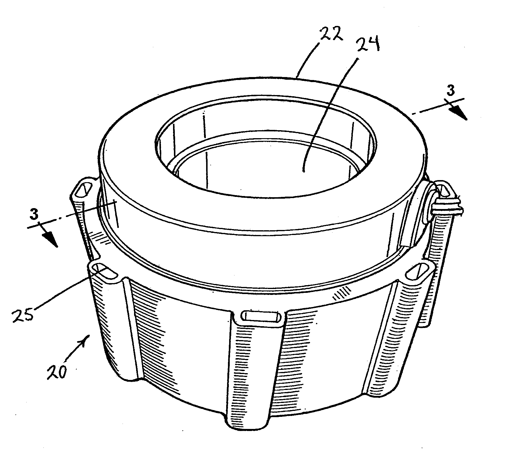
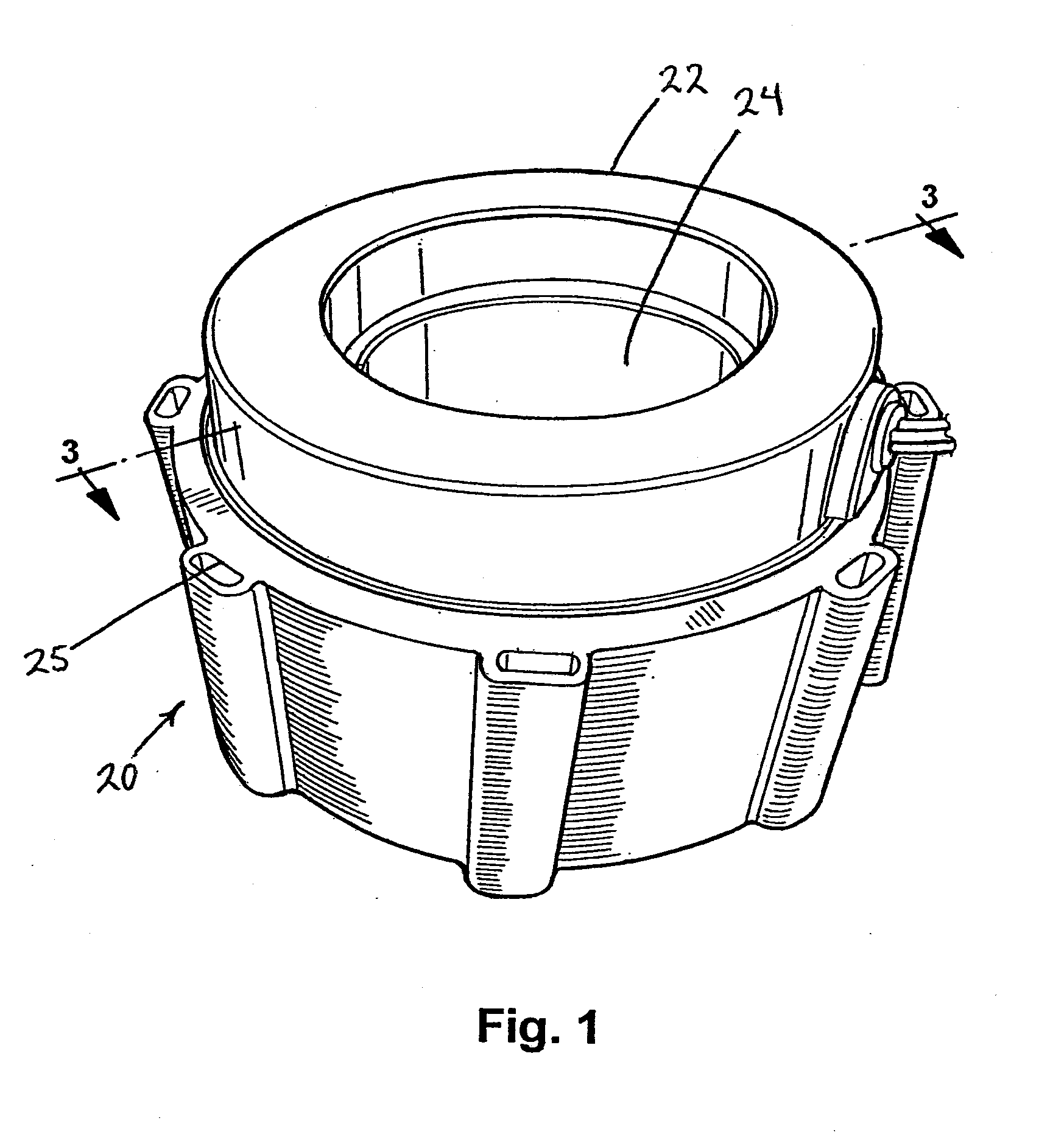
[0022]the invention, identified as “FORM 1,” is best illustrated in the cross sectional view provided by FIG. 3. In the configuration illustrated in FIG. 3, the end turns 26 at opposite ends of the wound stator arrangement are sealed by annular plastic end cups 22. Both of these cups 22 have essentially the same configuration, and include radially extending outer and inner circumferential flanges 46 and 48, circumferentially disposed radially inner and outer sides 50 and 52 extending axially with respect to the stator 20, and an annular base 54 interconnecting the sides 50 and 52. The stator inner diameter surface 30 is sealed by vacuum encapsulation or by way of a varnish and subsequent encapsulation. Testing has shown that the small amount of encapsulant on the stator inner diameter, aided by the much better support structure compared to the end turn area, results in significantly fewer encapsulant cracking problems at the stator inner diameter.

[0023]At least one of the end cups 2...

second embodiment

[0027]The axial tubes or necks 160 are appropriately dimensioned so that, upon placing the end cups 122 of the second embodiment over the end turns 26 at opposite ends of the wound stator arrangement, terminal ends 161 of the tubes or necks abut or nearly abut, so that the terminal ends 161 may be secured together adhesively, by heat bonding, or otherwise. In this way, the end cups 122 are secured to each other as well as to the longitudinally endmost stator surfaces, defined by the axially outermost stator laminations 28. FIG. 4 illustrates a seam 162 along which the terminal ends 161 of opposed end cups are secured together. Such a terminal end 161 is best shown in FIG. 5.

[0028]A fundamental result provided by using either the cups 22 of the first embodiment or the cups 122 of the second embodiment is to cover over the “ecap,” or encapsulant. Ecap, especially epoxy formulations, are found to crack upon cooling down when curing, and to continue to crack subsequently, especially whe...


PUM


Abstract

A stator arrangement particularly suitable for use in an air-cooled generator or other such electric machine includes a stator with an outer stator surface, an opening therein defining an inner stator surface, and longitudinally opposed stator end surfaces. Conductive coils are supported by the stator, and include end turns overlying the longitudinally opposed stator end surfaces. In order to block out environmental contaminants and prevent conductive coil shorting, protective barriers are mounted over the end turns and secured to the stator.

Description

CROSS-REFERENCE TO RELATED APPLICATION[0001]Attention is directed to commonly assigned U.S. patent application Ser. No. 13 / 005,010, filed Jan. 12, 2011, titled Coolant Flow Enhancing Device for Stator Coil End Turns of Fluid Cooled Electric Motor.BACKGROUND OF THE INVENTION[0002]1. Field of the Invention[0003]This invention concerns a stator arrangement, usable as part of a housingless generator or other assembly, in which at least one of the outer stator surfaces may be exposed to the surrounding environment to permit air cooling.[0004]2. Description of Related Art[0005]U.S. Pat. No. 3,353,041 to Little discloses a laminated rotor for an electric motor including steel end caps secured to rotor end laminations to cover rotor end windings and help prevent damage to the end windings. The entire disclosure of the Little ('041) patent is incorporated herein by reference as non-essential subject matter.SUMMARY OF THE INVENTION[0006]A stator arrangement according to the present invention ...

Claims


Application Information

Patent Timeline
Patent Type & Authority Applications(United States)
IPC IPC(8): H02K5/10
CPCH02K1/185H02K9/16H02K5/10H02K3/44H02K3/50
Inventor TRAGO, BRADLEY A.FIELDS, STEPHEN MARK
Owner KOLLMORGEN CORP
Why Eureka
Try Eureka