
Elongation measuring apparatus, elongation measurement system, and non-transitory medium

Active Publication Date: 2012-10-25
TSUBAKIMOTO CHAIN CO
View PDF12 Cites 11 Cited by
  • Summary
  • Abstract
  • Description
  • Claims
  • Application Information

AI Technical Summary

Benefits of technology

[0028]In the present invention, the elongation of the chain is outputted, thus allowing an operator or a user to recognize the elongation of the chain.
[0039]In the present invention, when the elongation of the chain exceeds the given value, information indicative of this fact is transmitted from the server to the computer of the user, thereby making it possible to prompt the user to replace the chain that should be replaced.

Problems solved by technology

However, in the foregoing method, a distance measured between the two rollers of the chain before use has to be preset in the computer, and therefore, the chain elongation cannot be detected when the distance measured between the two rollers before use is unknown.

Method used


Image

  • Elongation measuring apparatus, elongation measurement system, and non-transitory medium
  • Elongation measuring apparatus, elongation measurement system, and non-transitory medium
  • Elongation measuring apparatus, elongation measurement system, and non-transitory medium

Examples


embodiment 1

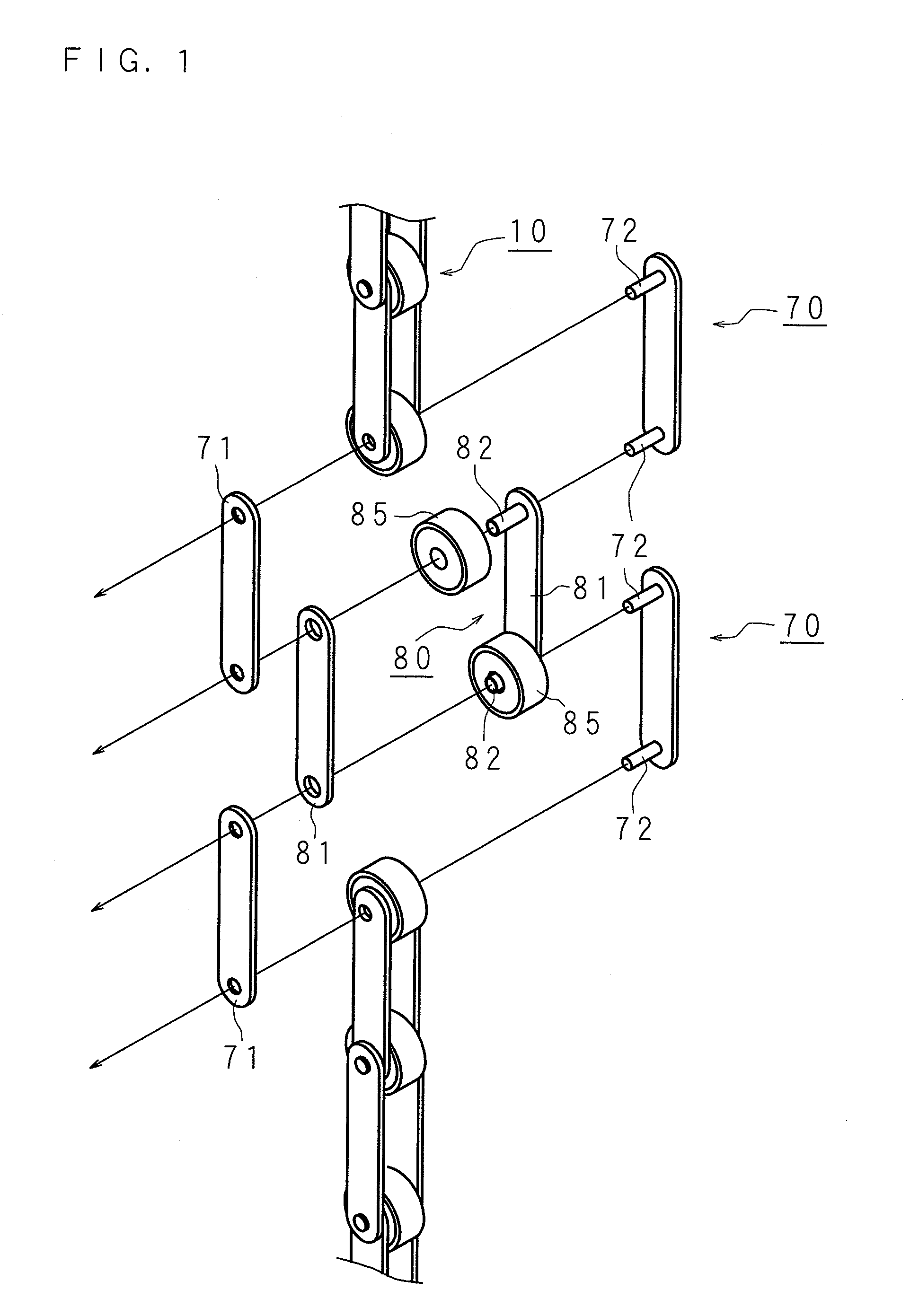
[0053]Hereinafter, the present invention will be described in detail with reference to the drawings illustrating an elongation measurement system according to Embodiment 1. FIG. 1 is an exploded view schematically illustrating a chain.

[0054]In FIG. 1, “80” denotes an inner link, and each inner link 80 includes two inner plates 81, 81 facing each other. Each inner plate 81 is formed by an elliptical flat plate member, and two holes are provided at ends of each flat plate member. Ends of two cylindrical bushings 82, 82 are interference fitted into the two holes of one of the inner plates 81, and the other ends of the bushings 82, 82 are interference fitted into the two holes of the other inner plate 81, thus connecting the two inner plates 81, 81 to each other. Annular rollers 85, 85 are rotatably externally fitted to the bushings 82, 82.

[0055]The inner links 80 are located inwardly of outer links 70. Each outer link 70 includes two outer plates 71, 71 facing each other. Each outer pl...

embodiment 2

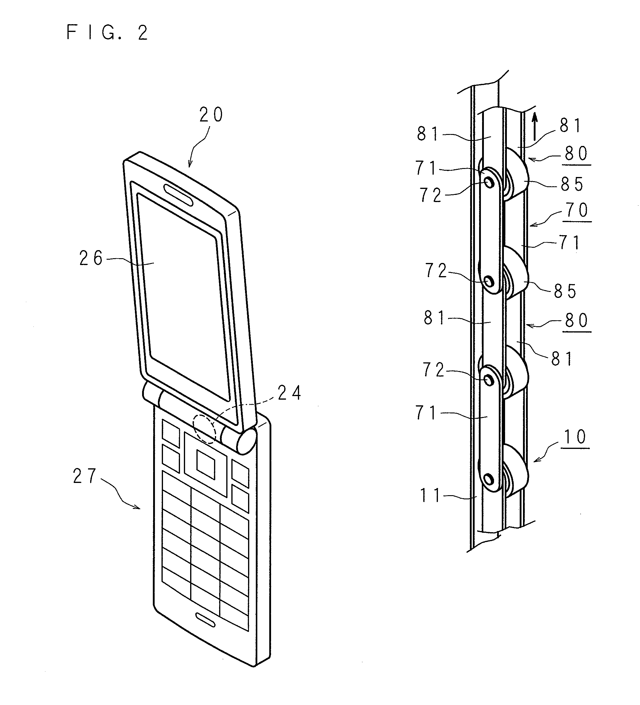
[0099]Hereinafter, the present invention will be described in detail with reference to the drawings illustrating an elongation measurement system according to Embodiment 2. In the elongation measurement system according to Embodiment 2, the terminal device 20 transmits image-taking data of the chain 10 to the server 40 together with image-taking position and image-taking time. Then, the server 40 calculates an elongation of the chain and returns the calculated elongation to the terminal device 20, and the elongation is displayed on the display section 26 of the terminal device 20.

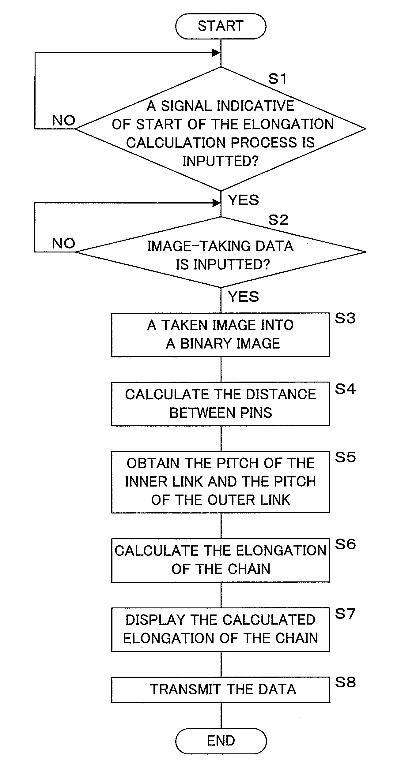
[0100]FIG. 9 is a flow chart describing a process for displaying the elongation of the chain 10, which is performed by the CPU 21 of the terminal device 20.

[0101]The CPU 21 of the terminal device 20 determines whether or not a signal indicative of start of the elongation calculation process is inputted by an operation performed on the operation section 27 (Step S41), and enters the standby mode until the si...


PUM


Abstract

The present invention provides an elongation mesuring appratus, an elongation measurement system and a non-transitory medium recording a computer program, which enable measurement of an elongation of a chain without presetting a distance between rollers before use. Based on an image of three or more pins, two adjacent inter-pin distances are each calculated. As a result of a comparison between the two calculated inter-pin distances, the longer distance is determined as a pitch of an inner link and the shorter distance is determined as a pitch of an outer link. The outer link is not elongated while only the inner link is elongated, and therefore, a ratio of a difference between both of the pitches to the pitch of the outer link is determined as an elongation of a chain.

Description

[0001]This application is the national phase under 35 U.S.C. §371 of PCT International Application No. PCT / JP2010 / 069697 which has an International filing date of Nov. 5, 2010 and designated the United States of America.BACKGROUND[0002]1. Technical Field[0003]When regular maintenance is performed on a chain in which a plurality of inner links and a plurality of outer links are alternately connected to each other so as to be wrapped around a sprocket and ends of the chain are coupled to each other via a joint link to carry out product conveyance or power transmission, the following method is performed. The joint link is removed, and the chain is detached from the sprocket; then, a measurement is performed on a length of the chain, and when a difference between an initial length and a length measured after use reaches a reference value, the chain is replaced, thus preventing occurrence of an accident. However, the foregoing method requires a lot of time and effort for detachment / attac...

Claims


Application Information

Patent Timeline
IPC IPC(8): G06K9/62
CPCB65G43/02F16G13/06G01B11/04G01B11/02
Inventor KOUNO, KOUJI
Owner TSUBAKIMOTO CHAIN CO
Learn More