

Reheat burner injection system
a technology of injection system and reheat burner, which is applied in the direction of combustion type, lighting and heating apparatus, combustion using lump and pulverulent fuel, etc., can solve the problems of high nox emission level and higher life cycle cos
Active Publication Date: 2012-11-01
ANSALDO ENERGIA SWITZERLAND AG
View PDF3 Cites 54 Cited by
- Summary
- Abstract
- Description
- Claims
- Application Information
AI Technical Summary
Problems solved by technology
As a result, there can arise high NOx emission levels and higher life cycle costs.
This criterion can pose challenges in obtaining appropriate distribution of the fuel across the burner exit area.
Method used
View moreImage
Smart ImageViewing Examples

Examples
embodiment 1
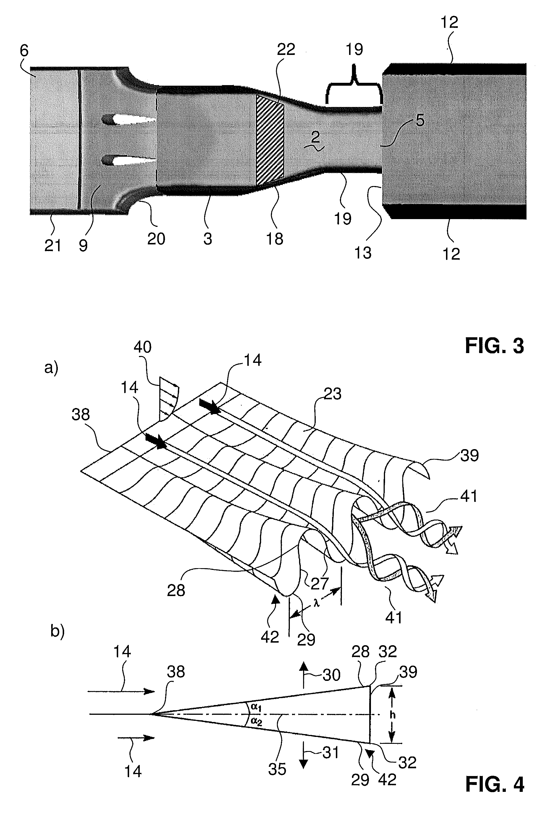
[0101]Staggering of lobes to eliminate vortex-vortex interactions. The vortex-vortex interactions result in not effectively mixing the fuel air streams.
embodiment 2
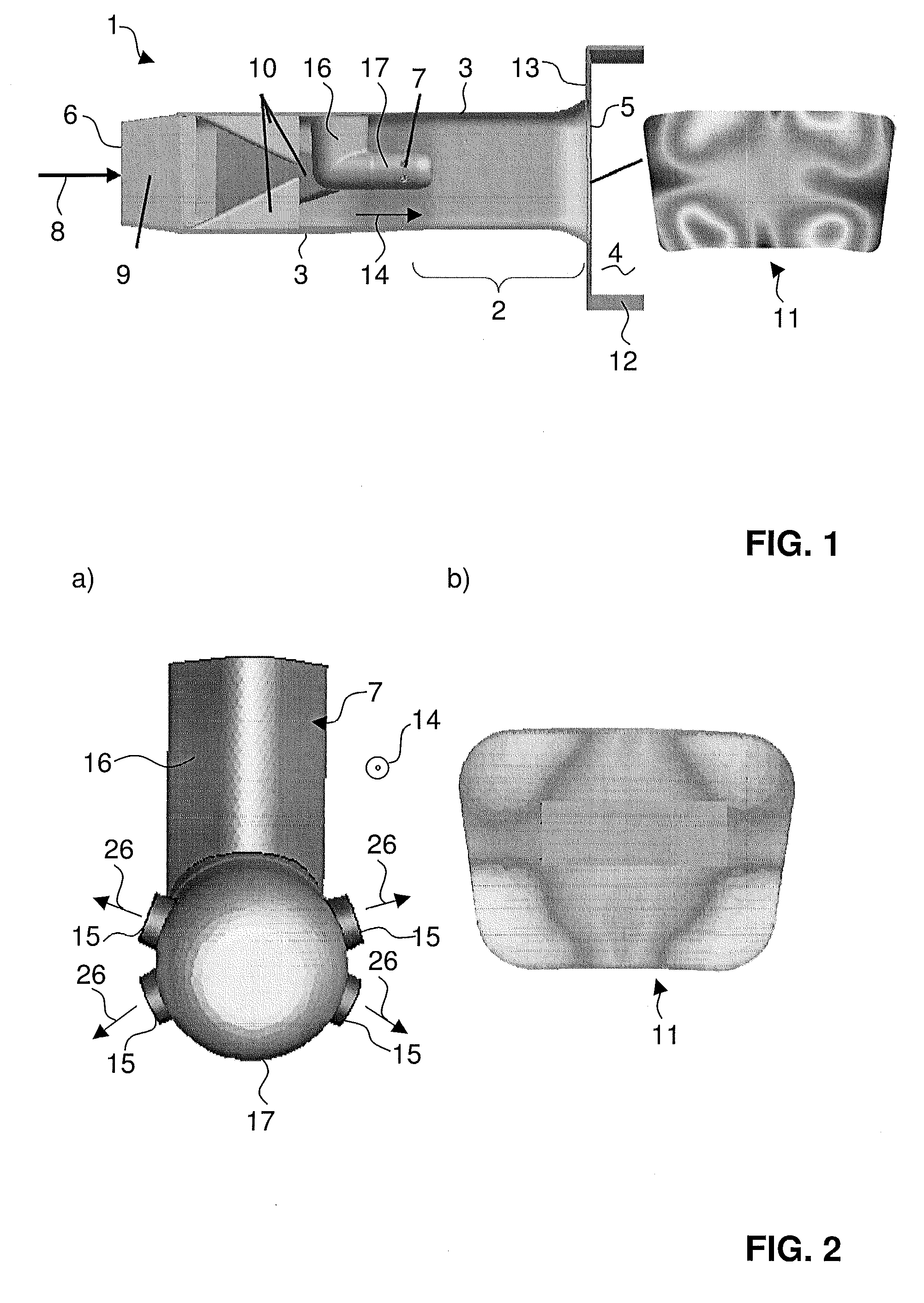
[0102]Careful placement and location of fuel injection on the lobes: Fuel jets can be placed in the areas of high shear regions in order to best utilize the turbulent dissipation for mixing.
embodiment 3
[0103]Inclined fuel injection in the lobes: This allows fuel to be injected in to the vortex cores.
Login to View More PUM
 Abstract
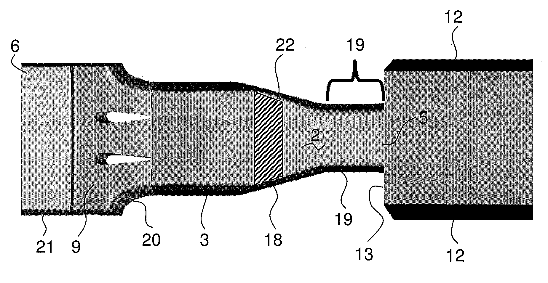
The disclosure relates to a burner for a combustion chamber of a gas turbine, with an injection device for the introduction of at least one gaseous and / or liquid fuel into the burner, wherein the injection device has at least one body which is arranged in the burner with at least one nozzle for introducing the at least one fuel into the burner, the at least one body being configured as a streamlined body which has a streamlined cross-sectional profile and which extends with a longitudinal direction perpendicularly or at an inclination to a main flow direction prevailing in the burner. The at least one nozzle has its outlet orifice at or in a trailing edge of the streamlined body, and with reference to a central plane of the streamlined body, the trailing edge is provided with at least two lobes extending in opposite transverse directions.
Description
RELATED APPLICATION[0001]This application claims priority as a continuation application under 35 U.S.C. §120 to PCT / EP2010 / 066522, which was filed as an International Application on Oct. 29, 2010 designating the U.S., and which claims priority to Swiss Application 01889 / 09 filed in Switzerland on Nov. 7, 2009. The entire contents of these applications are hereby incorporated by reference in their entireties.FIELD[0002]A burner is disclosed for a combustion chamber of a gas turbine, such as a secondary combustion chamber with sequential combustion having first and secondary combustion chambers, and with an injection device for the introduction of at least one gaseous and / or liquid fuel into the burner.BACKGROUND INFORMATION[0003]In order to achieve high efficiency, a high turbine inlet temperature is used in standard gas turbines. As a result, there can arise high NOx emission levels and higher life cycle costs. This can be mitigated with a sequential combustion cycle, wherein the co...
Claims
Login to View More Application Information
Patent Timeline
 Patent Type & AuthorityApplications(United States)
IPC IPC(8): F23R3/34F02C7/00F02C7/18
CPCF23R3/20F23R3/12
InventorSYED, KHAWARPOYYAPAKKAM, MADHAVANWINKLER, ANTONTHEUER, ANDRE
OwnerANSALDO ENERGIA SWITZERLAND AG