Shock absorbing device

Inactive Publication Date: 2012-11-01
MOBIUS PROTECTION SYST
View PDF14 Cites 7 Cited by
  • Summary
  • Abstract
  • Description
  • Claims
  • Application Information

AI Technical Summary

Benefits of technology

[0024]A further object of the invention is to disclose the step of reducing the shock effect performed by the energy absorber which is selected from the group consisting of a crushable column, a rolling torus, an inversion tube, a cutting shock absorber, a slitting shock absorber, a tube-and-die absorber; a rolling/flattening-a-tube absorber; a strap/rod/wire bender absorber, a wire-through-platen absorber, a deformable link absorber, an elongating a tube/strap/cable absorber, a tube flaring,

Problems solved by technology

Land mine explosions pose two serious threats to vehicle occupants.
First, the mines may contain projectiles which penetrate the underside of the vehicle and strike the occupants.
Secondly, the blast energy can cause very high accelerations to be imparted to the occupants.
Thus, the lighter occupants were at a hig

Method used


Image

  • Shock absorbing device
  • Shock absorbing device
  • Shock absorbing device

Examples


Embodiment Construction

[0042]The following description is provided, alongside all chapters of the present invention, so as to enable any person skilled in the art to make use of said invention and sets forth the best modes contemplated by the inventor of carrying out this invention. Various modifications, however, are adapted to remain apparent to those skilled in the art, since the generic principles of the present invention have been defined specifically to provide a shock absorbing chair and a method of using the same.

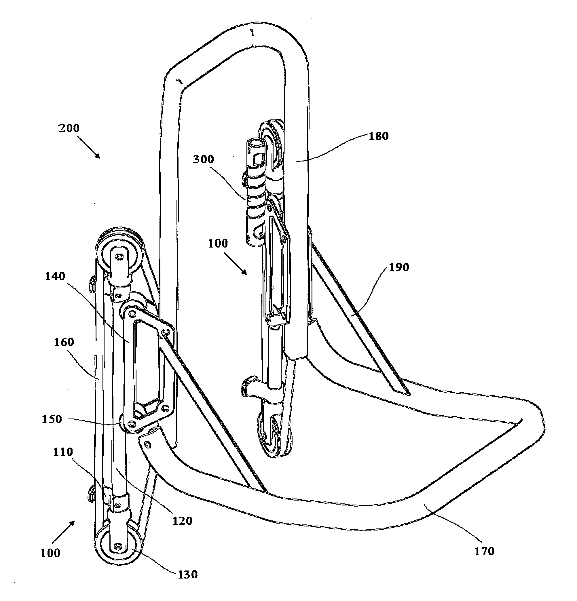
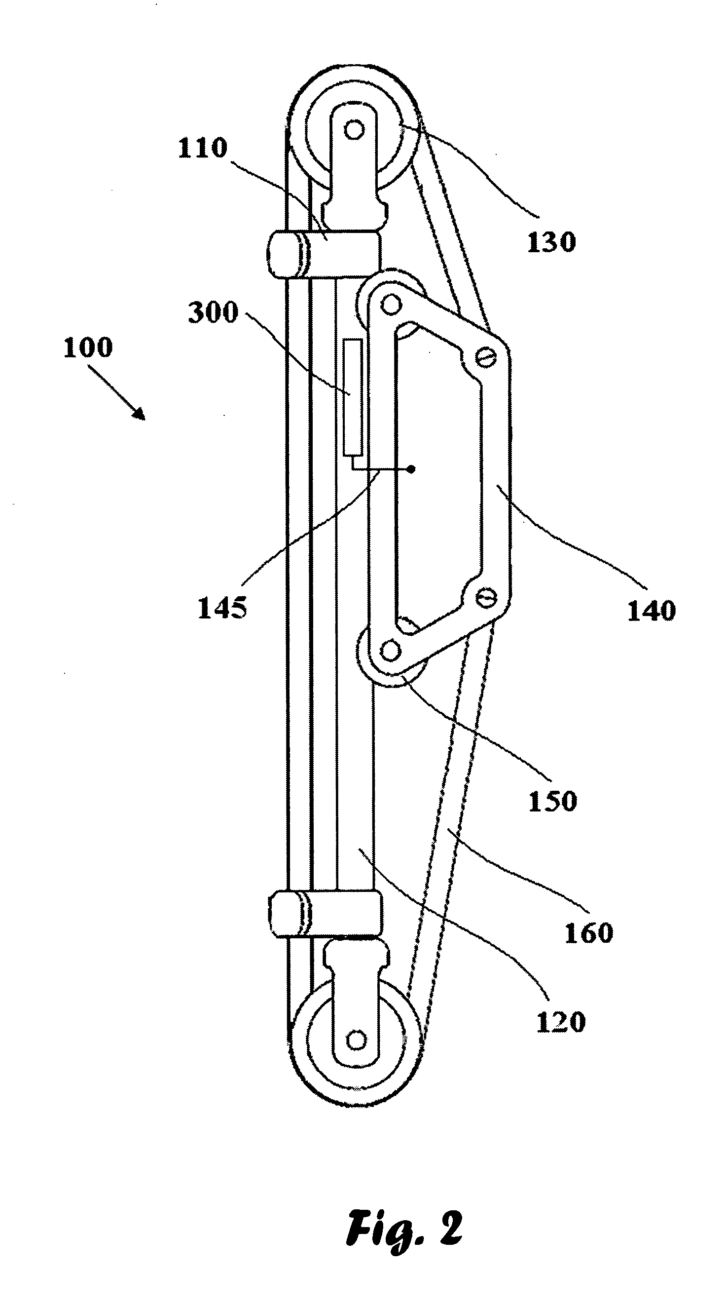
[0043]Reference is now made to FIG. 2, showing a shock absorbing device 100. The aforesaid device 100 comprises a distance bar 120 mechanically securable to a substantially vertical surface (not shown) by means of holding clips 110 which are rotatable relative to the distance bar 120. The distance bar 120 is provided with two pulleys at terminals thereof. An elongate carriage 140 is linearly movable along the distance bar 120 by means of rollers 150. An object of interest (not shown) whic...


PUM


Abstract

A shock absorbing device adapted for mounting at a substantially vertical surface is disclosed. The aforesaid device comprises (a) vertically spaced-apart two pulleys being mechanically securable to the vertical surface; (b) an elongate member; the elongate member provided with two terminals; the member adapted for reciprocative motion along the elongate member; the member adapted for mechanically securing a subject to be protected; (c) a wire connected to the terminals of the member and tensioned through the pulleys. The device further comprises an energy absorber. The movable elongate member is mechanically secured to the vertical surface by means the energy absorber

Description

REFERENCE TO RELATED PUBLICATION[0001]This application claims priority from U.S. provisional application 61 / 247,956, dated Oct. 2, 2009, which is hereby incorporated by reference in its entirety.FIELD OF THE INVENTION[0002]The present invention relates to a shock absorbing device, and, more specifically, to a shock absorbing device provided with an energy absorber adapted for plastic deformation.BACKGROUND OF THE INVENTION[0003]There is currently a great deal of interest in improving the safety of vehicles subject to mine blast loading or high impact crashes. Land mine explosions pose two serious threats to vehicle occupants. First, the mines may contain projectiles which penetrate the underside of the vehicle and strike the occupants. Secondly, the blast energy can cause very high accelerations to be imparted to the occupants. Many research efforts have centred on adding armour to the underside of a vehicle to reduce the penetration of projectiles and to either divert or absorb the...

Claims


Application Information

Patent Timeline
IPC IPC(8): B60N2/50F16M13/02B60N2/30F16F7/12
CPCB60N2/24B60N2/42736B60N2/4242
Inventor MINDEL, SHYHASSAN, ANANENGEL, DAVIDBAUM, MOSHE JACOB
Owner MOBIUS PROTECTION SYST
Why Eureka
Try Eureka