Turbine blade air film cooling structure and gas turbine adopting same

A technology of air film cooling and turbine blades, which is applied in the direction of blade support components, mechanical equipment, engine components, etc., can solve the problems of small coverage, loss of blade protection, poor cooling protection ability, etc., to improve cooling efficiency and improve Effect of air film coverage and cooling effect

Pending Publication Date: 2022-04-29
FULL DIMENSION POWER TECH
View PDF1 Cites 0 Cited by
  • Summary
  • Abstract
  • Description
  • Claims
  • Application Information

AI Technical Summary

Problems solved by technology

[0005] However, in the application process, from the perspective of the lowest processing and manufacturing costs, the cold air holes are generally set as circular holes or fan-shaped holes. The circular cold air holes are easy to break away from the surface of the blade at a low blowing ratio, and cannot be isolated The role of blades and high-temperature gas; fan-shaped cold air holes can still maintain adhering to the wall to form an air film at a high blowing ratio, but the air film is easily mixed with high-temperature gas during the downstream development process, so after a short distance the loss of protection for the leaves
[0006] In summary, the inventor believes that the air film in the related art has a small coverage area on the turbine blades and poor cooling protection ability

Method used


Image

  • Turbine blade air film cooling structure and gas turbine adopting same
  • Turbine blade air film cooling structure and gas turbine adopting same
  • Turbine blade air film cooling structure and gas turbine adopting same

Examples


Embodiment 1

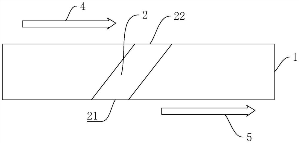
[0047] Such as Figure 7 and Figure 8 As shown, it is a turbine blade air film cooling structure, including the air film channel 2 opened on the surface of the turbine blade, the air film channel 2 is inclined, the air film channel 2 includes an inlet 21 and an outlet 22, and the inlet 21 is adjacent to the cooling The working medium 5 and the outlet 22 are adjacent to the high-temperature gas 4 .

[0048] A fluid oscillation generator 3 is arranged between the inlet 21 and the outlet 22. The cross-sectional dimension of the fluid oscillation generator 3 is larger than that of the air film channel 2, and the cross-sectional dimension of the fluid oscillation generator 3 suddenly increases. In this embodiment, the section of the fluid oscillation generator 3 is rectangular, and the distance between the fluid oscillation generator 3 and the inlet 21 is greater than the distance between the fluid oscillation generator 3 and the outlet 22 .

[0049] combine Figure 9 and Fig...

Embodiment 2

[0052] The difference between this embodiment and Embodiment 1 is that the fluid shock generator 3 is arranged in an arc shape perpendicular to the two sides of the gas film channel 2 (such as Figure 11 ).

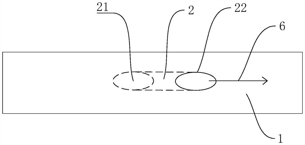
[0053] Such as Figure 11 and Figure 12 As shown, the cooling working medium 5 enters the fluid oscillation generator 3 from the inlet 21, and periodically oscillates inside the fluid oscillation generator 3, so that the direction of the outlet cold air 6 at the outlet 22 of the gas film channel 2 is periodically oscillated, The outlet cold air 6 forms periodic air film coverage on the side wall surface of the blade wall 1 adjacent to the high-temperature gas 4, which plays a better role in protecting the blade wall 1.

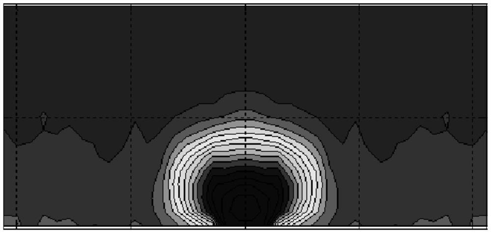
[0054] Such as Figure 13 As shown, the numerical simulation results show that the local cold air coverage of the film cooling hole based on fluid oscillation is enlarged, and there is good cold air coverage within the range of ±2.5 times the aperture...


PUM


Abstract

The invention relates to a turbine blade air film cooling structure and a gas turbine with the cooling structure.The air film cooling structure comprises an air film channel formed in the wall face of a turbine blade, and the air film channel comprises an inlet used for inputting a cooling working medium and an outlet used for outputting the cooling working medium; the cooling medium is fed between the high-temperature fuel gas and the blade wall surface to form a gas film; a fluid oscillation generator with the section size suddenly enlarged is arranged between the inlet and the outlet, a cooling working medium generates periodical oscillation flowing in the fluid oscillation generator and generates periodical oscillation at the outlet, and the turbine blade cooling device has the advantages that the coverage range of an air film on the turbine blade is enlarged, and the cooling effect of the turbine blade is improved.

Description

technical field [0001] The present application relates to the field of turbine blade cooling, in particular to a turbine blade film cooling structure and a gas turbine adopting the cooling structure. Background technique [0002] With the improvement of gas turbine design technology, the gas temperature at the inlet of the gas turbine turbine continues to increase, and the heat load faced by the turbine blades is extremely high, which has already exceeded the limit that high-temperature materials can withstand. In order to ensure the safe and reliable operation of the turbine blades, a complex cooling design is required to keep the temperature and stress distribution of the turbine blades at a reasonable level. [0003] At present, film cooling technology is mostly used for the cooling of turbine blades, that is, by spraying cooling fluid between the high-temperature gas and the surface of the turbine blades, the high-temperature gas is isolated from the turbine blades, and ...

Claims


Application Information

Patent Timeline
Patent Type & Authority Applications(China)
IPC IPC(8): F01D5/18
CPCF01D5/186
Inventor 张正秋徐克鹏陈春峰王文三蒋旭旭陈江龙杨珑张磊
Owner FULL DIMENSION POWER TECH
Why Eureka
Try Eureka