
Handle having a retaining element, the same having an attachment means which remains entirely inside a moving part

a technology of a retaining element and a moving part, which is applied in the direction of mechanical equipment, electrical locking circuits, lock applications, etc., can solve the problems of difficult manipulation of the outside of the machine, and achieve the effect of improving the invention

Active Publication Date: 2012-11-01
HUF HULSBECK & FURST GMBH & CO KG
View PDF5 Cites 8 Cited by
  • Summary
  • Abstract
  • Description
  • Claims
  • Application Information

AI Technical Summary

Benefits of technology

[0004]The problem addressed by the present invention is that of creating a handle wherein it is possible to further increase the protection against break-ins while simultaneously keeping the complexity of installation low.
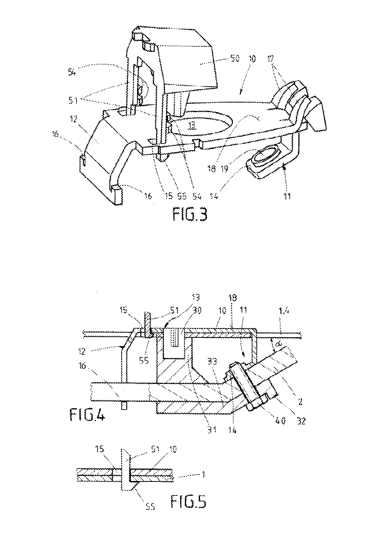
[0005]For this purpose, the invention suggests designing the retaining element in such a manner that the attachment means remains entirely inside the moving part, thereby making it possible to achieve increased protection against break-ins. An essential aspect of the invention is that the handle according to the invention offers virtually no points of attack where a potential tool can reach the attachment means, the same being entirely disposed inside the moving part, wherein the tool would be used to destroy the support, the attachment means, or other essential components attached to the support, for example. The support also is advantageously situated on the inside of the moving part, wherein the attachment means, the same establishing the connection between the support and the retaining element, constitutes the actual anchoring for the support. The attachment means can advantageously be designed as a screw element which provides a quickly established, reliable connection between the support and the retaining element inside the moving part. Because the attachment means is arranged entirely inside the moving part, manipulation thereof from the outside is made difficult. The configuration can particularly prevent manipulation, movement, or release of the handle on the moving part of the motor vehicle by means of releasing the attachment means in cases where this is undertaken for the purpose of entering the motor vehicle with malicious intent.

Problems solved by technology

Because the attachment means is arranged entirely inside the moving part, manipulation thereof from the outside is made difficult.

Method used


Image

  • Handle having a retaining element, the same having an attachment means which remains entirely inside a moving part
  • Handle having a retaining element, the same having an attachment means which remains entirely inside a moving part
  • Handle having a retaining element, the same having an attachment means which remains entirely inside a moving part

Examples


Embodiment Construction

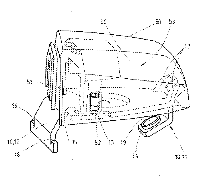
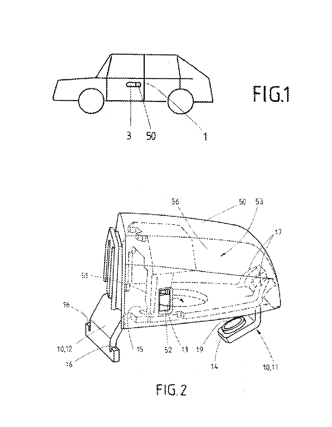
[0027]FIG. 1 shows a schematic illustration of a motor vehicle, having a handle on the door 1 thereof, wherein the handle has a handgrip 3 on the outer side thereof. A protective cap 50 is arranged on the side of the handgrip 3. A lock cylinder, by way of example, can be concealed being the protective cap 50, wherein a key can be manually inserted into the lock cylinder in order to unlock and / or to lock a lock of the door 1. This lock is not explicitly illustrated. As shown in FIGS. 2 through 4, the region of the handle on which the protective cap 50 is positioned is shown. The protective cap 50 is attached to a retaining element 10 and can be removed from the same. The retaining element 10 has different regions, such that this retaining element 10 functions inside the handle as a multi-function component. The retaining element 10 runs at least partially on the outer paneling, particularly on the door panel 4 of the door 1. In addition, the retaining element 10 is designed with an o...


PUM


Abstract

A handle for a moving part of a motor vehicle, particularly for a door, hatch, tailgate, or the like, having a retaining element which can at least partially be arranged on the outer paneling of the moving part, and having a support which can be arranged on the inside of the moving part and which is attached to the retaining element by means of an attachment means.

Description

TECHNICAL FIELD OF THE INVENTION[0001]The invention relates to a handle for a moving part of a motor vehicle, particularly for a door, hatch, tailgate, or the like, having a retaining element which can be arranged at least partially on the outer paneling of the moving part, and having a support which can be arranged on the inside of the moving part and which is attached on the retaining element by means of an attachment means.BRIEF DISCUSSION OF RELATED ART[0002]A device for securing a lock cylinder is disclosed in DE 10 2008 019 013.6. The device is attached on a moving part of a motor vehicle. In this case, the invention includes a retaining element which runs on the outer paneling of the moving part and which is attached on a support on the inside of the moving part.[0003]In this case, the retaining element has an opening, and at least the head region of the lock cylinder is accommodated in this opening. In addition, the retaining element has a flat structural shape running along...

Claims


Application Information

Patent Timeline
Patent Type & Authority Applications(United States)
IPC IPC(8): E05B3/00
CPCE05B85/06E05B79/02E05B79/06E05B17/14E05B77/44E05B81/90E05B85/16E05B77/34Y10T292/57
Inventor LENNHOFF, RALFBRAUNER, CHRISTOFMULLER, DIRKFROMME, ALEXANDER
Owner HUF HULSBECK & FURST GMBH & CO KG
Learn More