Automated Well Control Method and Apparatus

a well control and automatic technology, applied in the field of offshore well drilling, can solve the problems of increasing the number of kicks, reducing the efficiency and safety of a given operation, and exposing the subsea equipment to increasingly harsh conditions

Inactive Publication Date: 2012-11-01
HYDRIL USA DISTRIBUTION LLC
View PDF4 Cites 21 Cited by
  • Summary
  • Abstract
  • Description
  • Claims
  • Application Information

AI Technical Summary

Benefits of technology

[0005]The drilling system of this invention has features to automatically detect and control a kick or surge without requiring decisions to be made by operating personnel. The invention consists of sensors and an automatic control system that monitors and performs actions autonomously based on the sensor inputs. In a given embodiment there may exist a multitude of sensor combinations depending on the needs of the particular drilling operation. For example, in one embodiment there may exist a sensor to monitor return flow rate. The signals from the return flow rate sensor may be transmitted conventionally, such as through wires and fiber optic sensors that may be part of the umbilical leading to the platform. Ideally, the return flow rate sensor will indicate the flow rate at all times that exist within the wellhead assembly. An increase in flow rate sensed by the return flow rate sensor may indicate a kick. Additional sensor inputs such as inflow rate, temperature, wellhead bore pressure, string weight change, rate of penetration, torque, and various other sensors may all be monitored for additional indications of a kick or surge condition. Certain sets of sensor conditions may cause the control system to perform autonomous actions to lessen or stop the kick. For example, an indicated kick condition may cause the control system to alert operation personnel and subsequently initiate emergency procedures. These procedures may include an emergency disconnect sequence or the initiation of a wellbore shut-in sequence.

Problems solved by technology

This renders the subsea equipment to increasingly harsh conditions such as higher pressures and increased temperatures.
These harsher conditions can cause an increase in the number of kicks and hence decrease the efficiency and safety of a given operation.
For example, an indicated kick condition may cause the control system to alert operation personnel and subsequently initiate emergency procedures.

Method used


Image

  • Automated Well Control Method and Apparatus
  • Automated Well Control Method and Apparatus
  • Automated Well Control Method and Apparatus

Examples


Embodiment Construction

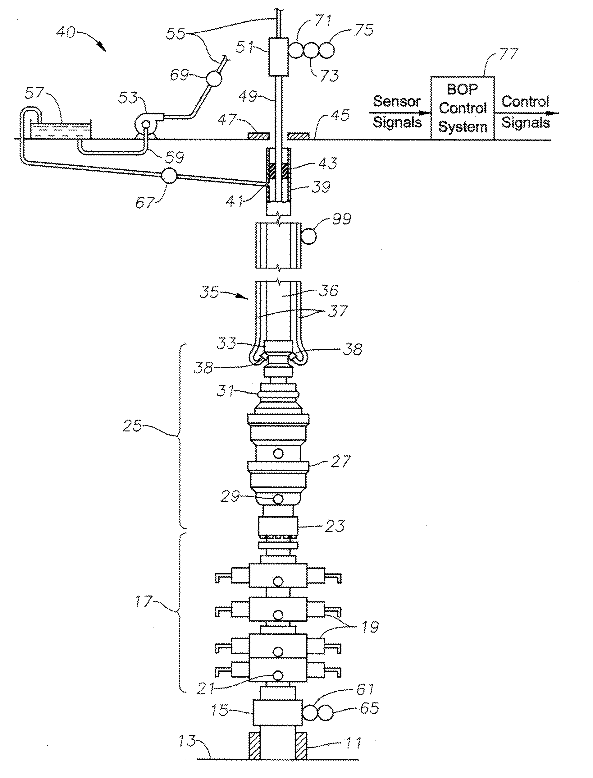
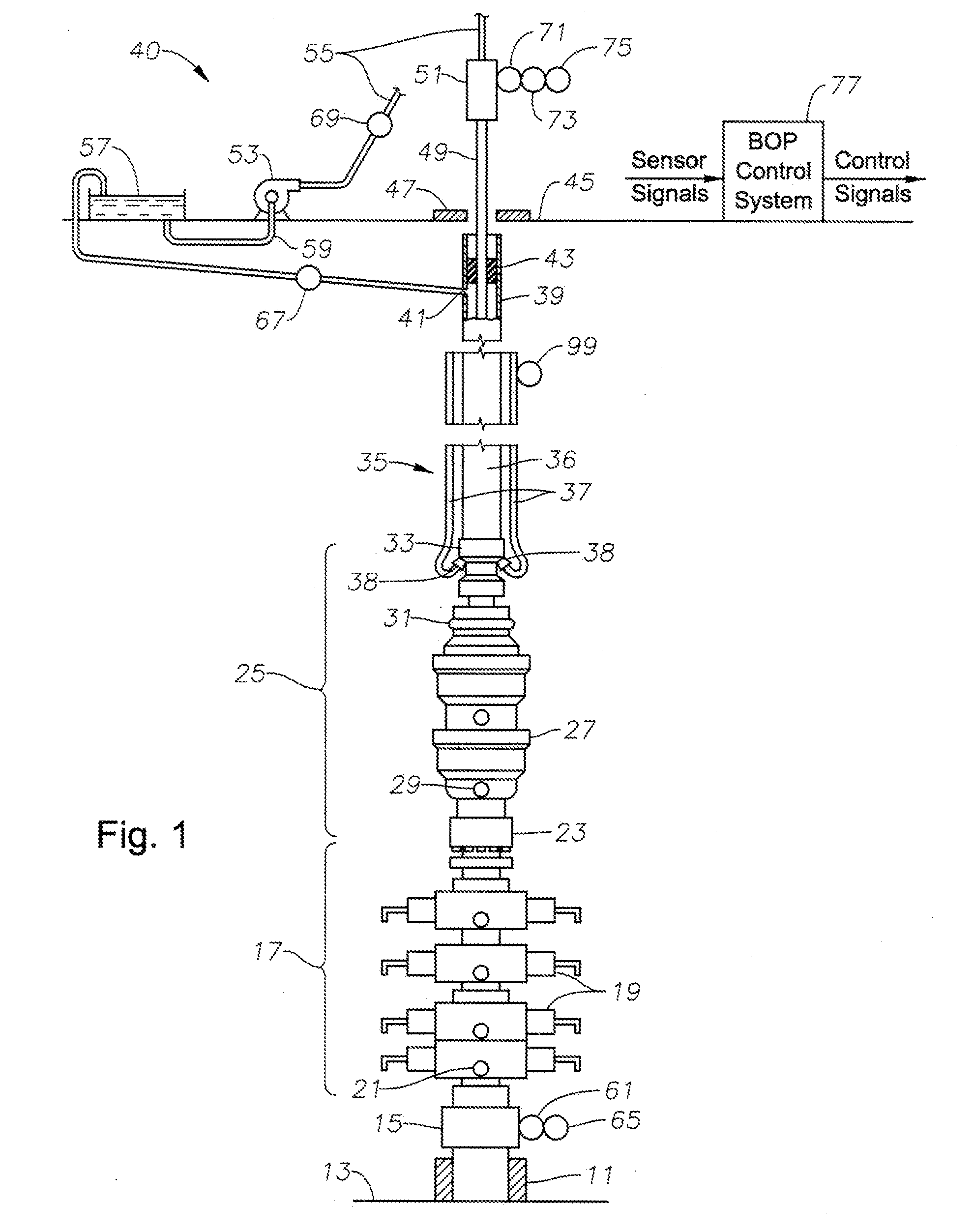
[0009]FIG. 1 illustrates a subsea well being drilled or completed. The well has been at least partially drilled, and has a subsea wellhead assembly 11 installed at sea floor 13. At least one string of casing (not shown) will be suspended in the well and supported by wellhead assembly 11. The well may have an open hole portion not yet cased, or it could be completely cased, but the completion of the well not yet finished.

[0010]A hydraulically actuated connector 15 releasably secures a blowout preventer (BOP) stack 17 to the wellhead housing assembly 11. BOP stack 17 has several ram preventers 19, some of which are pipe rams and at least one of which is a blind ram. The pipe rams have cavities sized to close around and seal against pipe extending downward through wellhead housing 11. The blind rams are capable of shearing the pipe and affecting a full closure. Each of the rams 19 has a port 21 located below the closure element for pumping fluid into or out of the well while the ram 19...


PUM


Abstract

A drilling control system monitors and compares drilling and completion operation sensor values and autonomously acts in response to conditions such as a kick or surge. Sensors in various combinations may monitor return fluid flow rate, fluid inflow rate, wellhead bore pressure, temperature of returning fluid, torque, rate of penetration and string weight change. The control system has corresponding control logic to monitor, warn and act based on the sensor inputs. The actions may include the warning of support personnel, closing an annular blowout preventer, shearing drill pipe using a ram shear, pumping heavier fluid down choke and kill lines, disconnecting the riser or various other actions.

Description

CROSS-REFERENCE TO RELATED APPLICATION[0001]This application claims the benefit of U.S. Provisional Application No. 61 / 479,203 filed on Apr. 26, 2011.FIELD OF THE INVENTION[0002]This disclosure relates in general to offshore well drilling and in particular to an automated method for controlling a subsea well during drilling procedures.BACKGROUND OF THE INVENTION[0003]The future of oil and gas exploration lies in deep waters and greater depth under the seabed. This renders the subsea equipment to increasingly harsh conditions such as higher pressures and increased temperatures. These harsher conditions can cause an increase in the number of kicks and hence decrease the efficiency and safety of a given operation. This calls for designing a subsea automatic control system for this widened high pressure and high temperature envelope. A control system which is capable of monitoring and logically controlling the equipment and tools can lead to a more reliable, safer, and more efficient su...

Claims


Application Information

Patent Timeline
Patent Type & Authority Applications(United States)
IPC IPC(8): G01V3/00
CPCE21B47/10E21B21/08E21B47/001
Inventor MILNE, ERIC L.EBENEZER, JOSEPH P.
Owner HYDRIL USA DISTRIBUTION LLC
Why Eureka
Try Eureka