Remote Control of Illuminating Headlamp

a technology for remote control and illumination headlamps, which is applied in the direction of semiconductor devices for light sources, lighting and heating apparatus, and support devices for lighting, etc. it can solve the problems of cumbersome optical cables attached to headsets, inconvenient use, and inability to mount illumination sources on headsets. , to achieve the effect of reducing the amount of tim

Active Publication Date: 2012-11-01
DESIGNS FOR VISION
View PDF6 Cites 43 Cited by
  • Summary
  • Abstract
  • Description
  • Claims
  • Application Information

AI Technical Summary

Problems solved by technology

While the fiber optical cable attached to the headset is cumbersome and may be inconvenient to the user, the power requirements and heat output of metal halide and xenon bulbs make it impractical for these illumination sources to be mounted on the headset.
The use of two LEDs also adds weight, cost and complexity to the device.
However, this patent application provides little detail as to implementation.
However, illumination is not uniform over the target area.
However, in the field of medical illumination devices when a doctor, surgeon or dentist, for example, utilizes a headlamp as described herein, the doctor, surgeon or dentist (i.e., a user) is in a sterilized state and cannot easily adjust the intensity of light.
That is, once the illumination device is turned-on and the user (i.e., doctor, surgeon or dentist) is in a sterile state, the user is no longer able to control the intensity of the illumination from the illumination device, without having to re-sterilize himself or herself.
In addition, leaving the light turned-on at a full intensity decreases the amount of time that the illumination device may provide the desired illumination as these illumination devices are typically operated on a battery power.

Method used


Image

  • Remote Control of Illuminating Headlamp
  • Remote Control of Illuminating Headlamp
  • Remote Control of Illuminating Headlamp

Examples


Embodiment Construction

[0031]It is to be understood that the figures and descriptions of the present invention described herein have been simplified to illustrate the elements that are relevant for a clear understanding of the present invention, while eliminating, for purposes of clarity many other elements found in illuminating headsets. However, because these elements are well-known in the art, and because they do not facilitate a better understanding of the present invention, a discussion of such element is not provided herein. The disclosure herein is directed to also variations and modifications known to those skilled in the art.

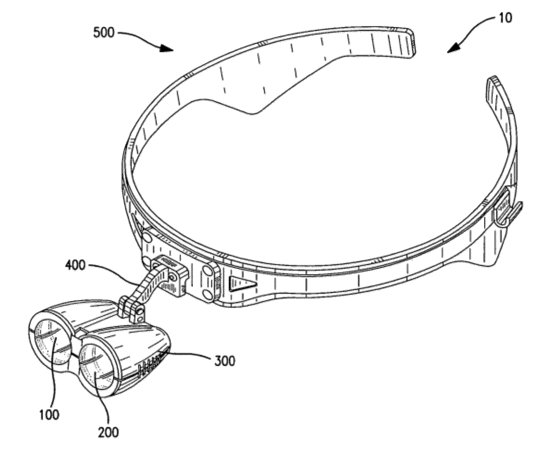
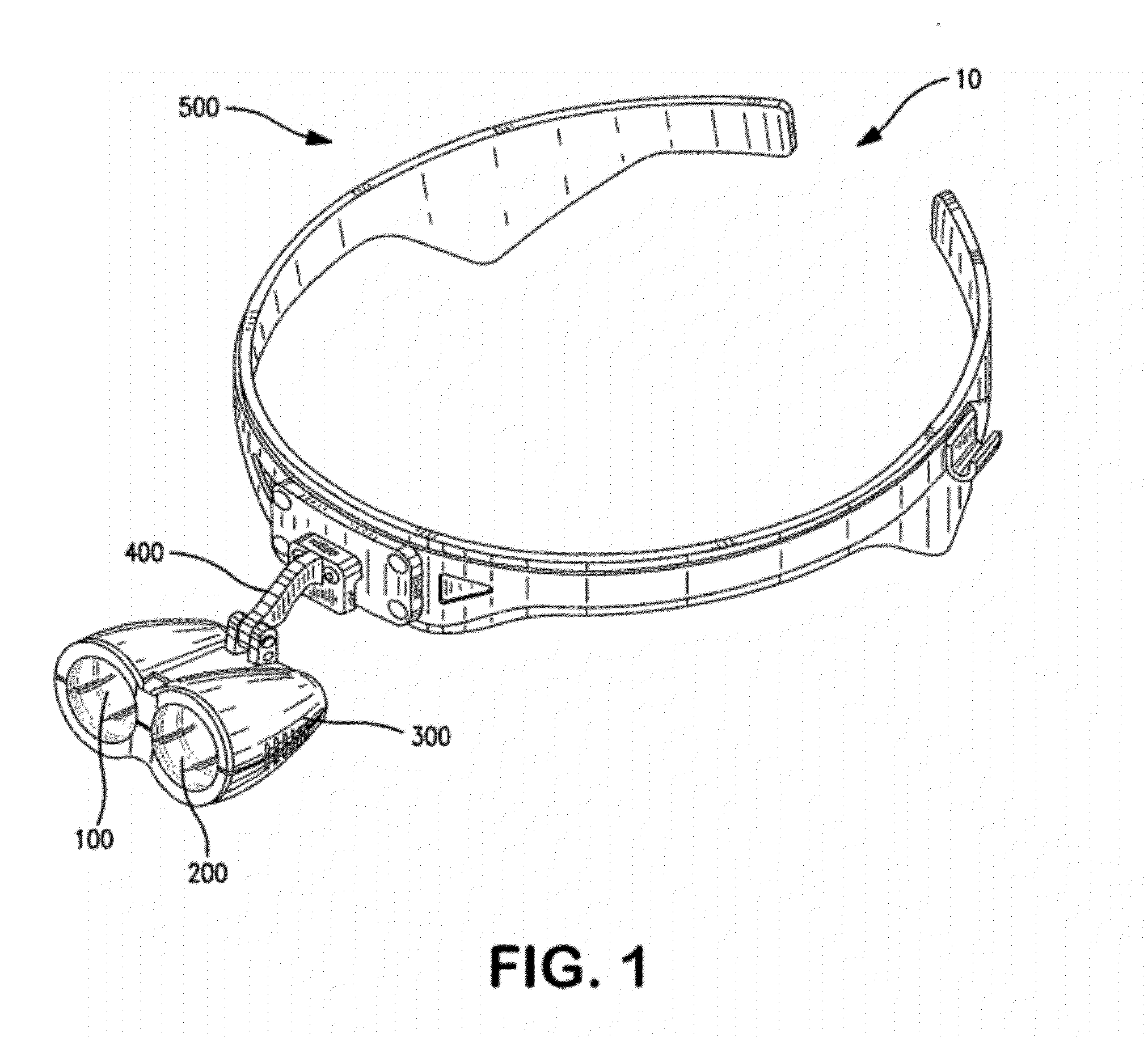
[0032]FIG. 1 represents an illuminating headset assembly. Headband assembly 10 includes generally two light-emitting units, or illumination devices, 100, 200, within housing 300. Illumination devices 100, 200 are supported relative to one another with housing 300, which is attached to assembly 10 by bar 400. Illumination devices 100, 200 are adapted to emit light in relativel...


PUM


Abstract

A remote control operation of an illuminated unit attached to a headset consisting of a headband and at least one optical device providing illumination at a known distance from said optical device attached to said headband is disclosed. The remote control unit incorporates a sensing unit that causes power to be switched on and off by the detection of motion in front of the sensing unit. In addition, the illumination may be increased or decreased based on a signal strength of a detected remote sensing signal.

Description

CLAIM OF PRIORITY[0001]This application claims, pursuant to 35 USC §120, priority to, and the benefit of the earlier filing data, as a Continuation-in-Part, of that patent application entitled “Illuminating Headlamp Providing Substantially Uniform Illumination,” filed on Feb. 1, 2010 and afforded Ser. No. 12 / 658,025, now U.S. Pat. No. ______, which is a continuation of, and claims priority to, that patent application, entitled “Illuminating Headlamp Providing Substantially Uniform Illumination,” filed on Mar. 3, 2008 and afforded Ser. No. 12 / 074,370, now U.S. Pat. No. 7,690,806, which claimed the benefit of the earlier filing date, pursuant to 35 USC §119(e), to that patent application entitled “Illuminating Headlamp and Method of Illumination,” filed on Mar. 30, 2007, and afforded Ser. No. 60 / 921,150, the contents of each of which are hereby incorporated by reference herein.[0002]In addition, this application is further related to that patent application entitled “Illumination Asse...

Claims


Application Information

Patent Timeline
Patent Type & Authority Applications(United States)
IPC IPC(8): F21V21/084H05B44/00
CPCF21L14/00F21V14/045F21V23/0435Y10S362/802H05B33/0842H05B37/0272F21Y2101/02F21Y2115/10H05B45/00H05B47/19H05B47/115Y02B20/40
Inventor FEINBLOOM, RICHARD E.BRAGANCA, KENKOSCHEKA, KENNETH
Owner DESIGNS FOR VISION
Why Eureka
Try Eureka