Mixing apparatus

a technology of mixing apparatus and mixing spout, which is applied in the direction of mixers, chemistry apparatus and processes, and mixing, etc., can solve the problems of insufficient mixing mass residues, and achieve the effect of strong turbulence of the mixing spou

Inactive Publication Date: 2012-11-01
HAAS FOOD EQUIP
View PDF12 Cites 9 Cited by
  • Summary
  • Abstract
  • Description
  • Claims
  • Application Information

AI Technical Summary

Benefits of technology

[0015]The inventive design of the mixing apparatus has a host of advantages for the construction and design of different-sized mixing apparatuses.
[0016]Compared with known mixing apparatuses in which the single-shaft agitator provides an annular stator which surrounds the rotor on the outer side and is rigidly connected to the bottom of the mixing container, the following advantages can be listed.
[0020]The inventive design of the mixing apparatus allows the rotor body of the agitator, which rotor body is disposed in the cylindrical mixing container, to be significantly enlarged without having to take into account an annular stator body surrounding the rotor body on the outer side, which stator body, in the known agitators equipped with stator and rotor, must likewise not only itself be enlarged in accordance with the enlargement of the rotor body, but must also be accommodated as an enlarged, annular stator body between the outer side of the already enlarged rotor body and the container wall of the cylindrical mixing container.
[0032]This embodiment of the mixing apparatus provides an impact element which is fixedly disposed in the mixing container, reaches from above into the mixing spout generated by the rotating rotor body and extending upward from the rotor body, and ensures a strong turbulence of the mixing spout.
[0037]This embodiment allows the position of the impact element in the mixing container to be adjusted in accordance with the height of the mixing spout generated in the mix product by the rotating rotor body. This configuration is of advantage when the mixing container is only partially filled. In this case, the mixing spout generated by the rotating rotor body does not extend upward from the rotor body to the maximum fill level height of the mixing container. The impact element can be displaced downward by vertical displacement of the bridge in the mixing container and can then be fixed to the mixing container in the region of the upper end of the mixing spout.
[0039]This configuration, too, is of advantage in respect of an only partially filled mixing container, because the bridge provided with an impact element can be adjusted in terms of its height position in the mixing container by displacement of the vertical rails to the height of the mixing spout generated by the rotating rotor body.

Problems solved by technology

If the mixing containers of the known mixing apparatuses are only partially filled with the baking preparation to be produced, then, even though the predominant part of the total mass is well mixed, inadequately mixed mass residues can also be left in the middle of the mixing container or on the container wall, which must then be removed from the mixing container separately from the well-mixed main quantity of baking preparation.

Method used


Image

  • Mixing apparatus
  • Mixing apparatus
  • Mixing apparatus

Examples


Embodiment Construction

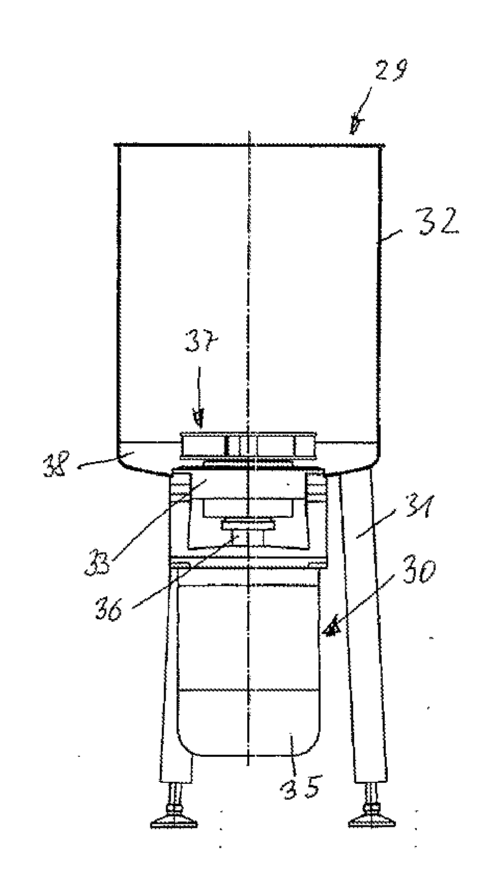
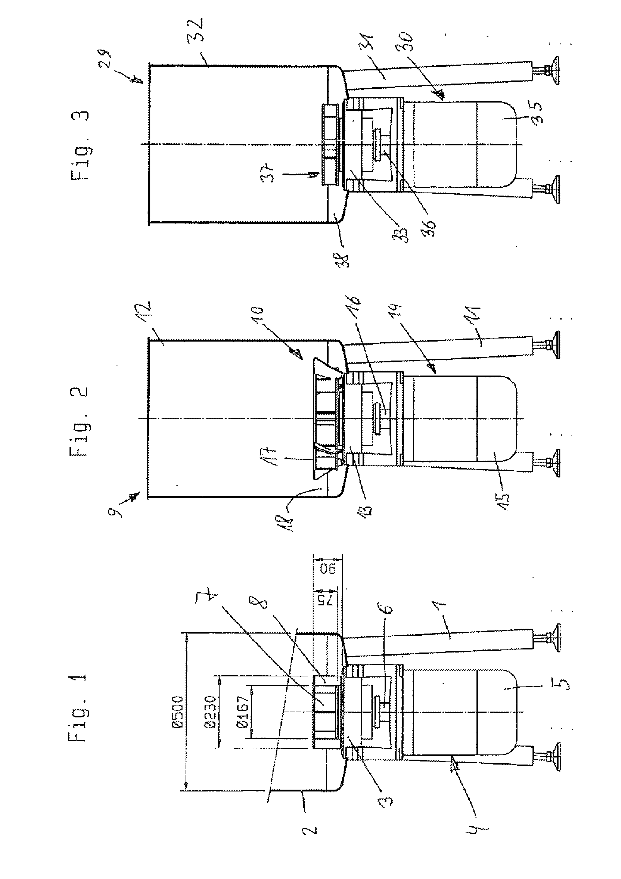
[0077]FIGS. 2, 8, 9 and 11 to 13 show an inventive mixing apparatus 9 having an inventive agitator 10.

[0078]The mixing apparatus 9 has a stand 11, which stands on the floor. The stand 11 supports an upwardly open, cylindrical mixing container 12, which is disposed in upright position in the upper part of the mixing apparatus 9. A circular plate 13, fastened to the stand 11, forms the bottom of the mixing container 12. The stand 11 supports a single-shaft agitator 14 disposed in the lower part of the mixing apparatus 9. The agitator 14 has a drive motor 15, which is fastened to the stand 11 and has a vertically disposed drive shaft, which, as the agitator shaft 16, projects upward into the mixing container 12. The agitator 14 has just a single agitating tool, disposed in the mixing container 12. This agitating tool is a rotor body 17 fastened to the upper end of the agitator shaft 16. In the mixing container 12, the rotor body 17 is surrounded by an outer, annular free space 18, whic...


PUM


Abstract

A mixing device has a frame, a cylindrical mixing container that is open toward the top, and a single-shaft agitator. A vertical agitator shaft extends into the mixing container from beneath. The agitator is an agitator without a stator and includes a rotor body arranged just above the container bottom in the mixing container. The rotor body is surrounded by a ring-shaped clearance between the rotor body and the container wall. Above the base plate fastened to the agitator shaft, the rotor body is provided with an inner clearance above the agitator shaft, mixing blades vertically arranged about the clearance, and flow channels arranged between the blades. The channels are delimited toward the top by a cover plate that is connected to the upper edges of the mixing blades. The cover plate is formed with a void arranged in the center and above the inner clearance.

Description

[0001]The invention relates to a mixing apparatus having a stand which supports an upwardly open, cylindrical mixing container, which is disposed in upright position in the upper part of the mixing apparatus, and a single-shaft agitator, which is disposed in the lower part of the mixing apparatus and has a vertically disposed agitator shaft to which an agitating tool, which is disposed in the mixing container just above the container bottom and is configured as a rotor body, is fastened.FIELD OF THE INVENTION[0002]In such mixing apparatuses are produced large quantities of shapeless masses, which consist mainly of water and flour, generally have a liquid to pasty consistency and from which edible, baked products, or baked products not intended for consumption, are subsequently produced in a baking process.[0003]Shapeless masses of this kind are, for example, the liquid baking preparations which are used in the baking methods associated with wafer baking technology.[0004]The liquid b...

Claims


Application Information

Patent Timeline
Patent Type & Authority Applications(United States)
IPC IPC(8): B01F7/16
CPCA21C1/02B01F7/00241B01F2215/0431B01F7/163B01F7/1685B01F7/162B01F27/111B01F27/811B01F27/808B01F27/862
Inventor HAAS, JOHANNESHAAS, JOHANNHAAS, JOSEFJIRASCHEK, STEFANDRAPELA, NORBERTBREYER, MARKUSTIEFENBACHER, KARL
Owner HAAS FOOD EQUIP
Why Eureka
Try Eureka