Method of forming a heat dissipating structure

a heat dissipating structure and extrusion molding technology, applied in the direction of manufacturing tools, semiconductor/solid-state device details, lighting and heating apparatus, etc., can solve the problems of difficulty in rapidly producing ventilated structures, and achieve the effect of enhancing the air-cooling efficiency of the heat dissipating structur

Inactive Publication Date: 2012-11-08
MITAC TECH CORP
View PDF6 Cites 4 Cited by
  • Summary
  • Abstract
  • Description
  • Claims
  • Application Information

AI Technical Summary

Benefits of technology

[0009]In the prior art, the problem that the existence of the fins causes difficulties on rapidly producing ventilated structures. By forming cut channels, the present invention rapidly forms massive cut through slots on a heat dissipating structure that has fins extended outward, thereby enhancing the air-cooling efficiency of the heat dissipating structure.

Problems solved by technology

In the prior art, the problem that the existence of the fins causes difficulties on rapidly producing ventilated structures.

Method used


Image

  • Method of forming a heat dissipating structure
  • Method of forming a heat dissipating structure
  • Method of forming a heat dissipating structure

Examples


first embodiment

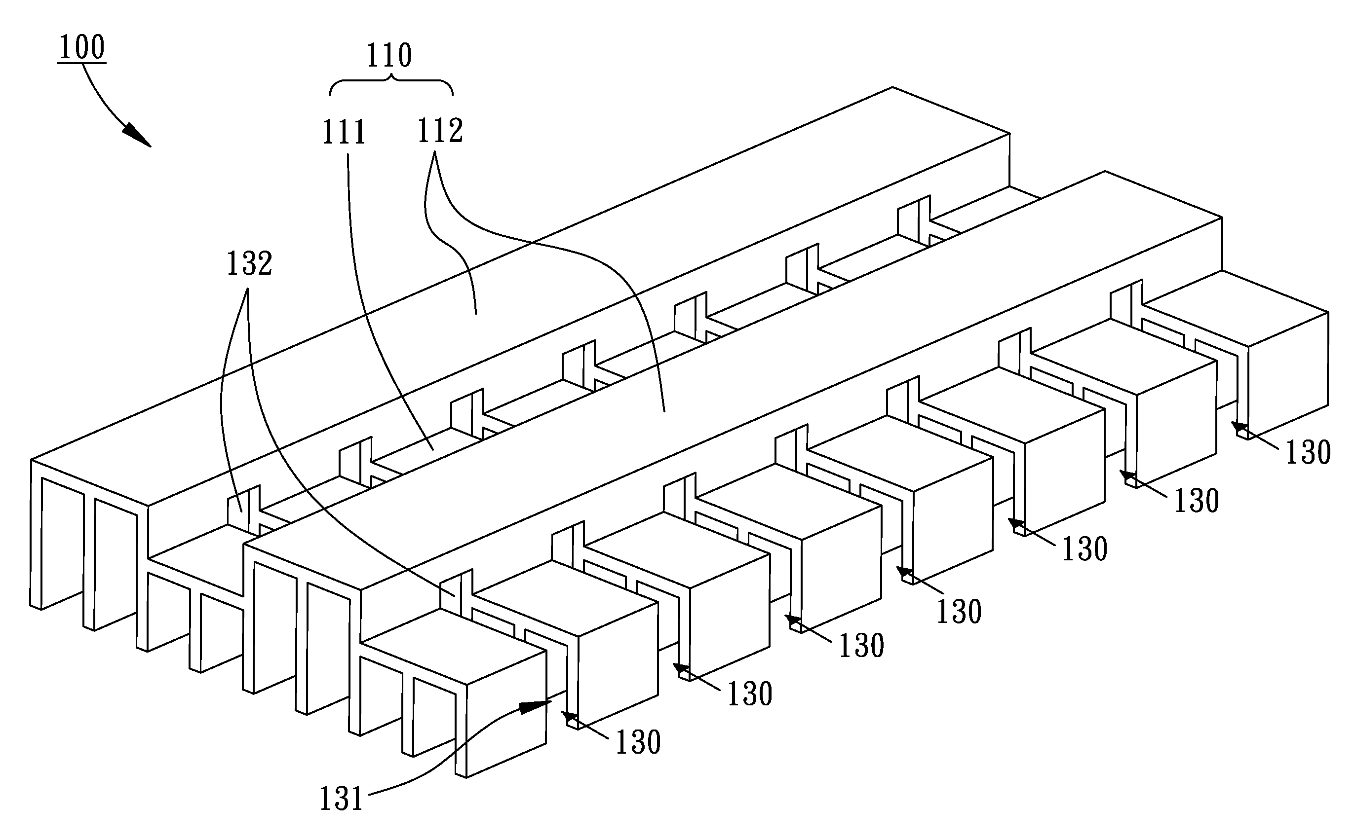
[0034]Referring to FIGS. 2, 3, and 4, a heat dissipating structure 100 according to the present invention is shown. The heat dissipating structure 100 includes an extrudate 110 and a plurality of fins 120, wherein the extrudate 110 and the fins 120 are formed monolithically by extrusion molding, and cooling air can flow through the extrudate 110 to enhance the air-cooling effect.

[0035]FIG. 5A is a cross-sectional view along line A-A′ in FIGS. 3 and 4. As shown in FIG. 5A, the extrudate 110 is formed by extrusion molding, the extrudate 110 can be a single sheet or a tubular structure. The extrudate 110 includes a plurality of bent portions 111 and a plurality of connecting portions 112 disposed alternately, and the bent portions 111 and connecting portions 112 extend in a longitudinal direction of the extrudate. The connecting portions 112 are provided for connecting the adjacent bent portions 111, and the bent portions 111 protrude from a surface of the extrudate 110. Since the extr...

second embodiment

[0043]FIGS. 8, 9, 10, and 11 a heat dissipating structure 200 according to the present invention is shown. The heat dissipating structure 200 includes an extrudate 210 and a plurality of fins 220, wherein the extrudate 210 and the fins 220 are monolithically formed by extrusion molding. The extrudate 210 includes a plurality of bent portions 211 and a plurality of connecting portions 212 disposed alternately, and the bent portions 211 and connecting portions 212 extend in a longitudinal direction. The connecting portions 212 are provided for connecting the adjacent bent portions 211, and the bent portions 211 protrude from a surface of the extrudate 210. The bent portion 211 includes a first protruding portion 2111 and a second protruding portion 2112 adjacent to each other on the cross-section, wherein the height of the first protruding portion 2111 protruding from the connecting portions 212 is larger than that of the second protruding portion 2112 protruding from the connecting p...

third embodiment

[0048]Referring to FIGS. 18, 19, and 20, the heights of the cutting lines of cut channels 330 determine whether cut-through slots 332 are formed at the bent portions by the cutting tool 900 as well as the cutting depths of the cut-through slots 332. The heights of the bent portions are unequal. When the cutting tool 900 is fed toward the surface of the extrudate 310, the fins 320 are cut at first, then the bent portions having relative higher height are cut to form the cut-through slots 332, and afterward the bent portions 311 having relative lower height are cut. In the third embodiment, the bent portions at least include a first bent portion 3111, a second bent portion 3112, and a third bent portion 3113. The first bent portion 3111, the second bent portion 3112, and the third bent portion 3113 are designated for illustration, instead of limiting the number of the bent portions.

[0049]Referring to FIG. 18, when the cutting tool 900 is continuously fed to make the cutting depths of ...


PUM

PropertyMeasurementUnit
heataaaaaaaaaa
heightaaaaaaaaaa
heightsaaaaaaaaaa

Abstract

A forming method for a heat dissipating structure is provided. According to the method, an extrudate is formed by extrution molding, wherein the extrudate includes protruding bending portions extending in parallel. Fins are extruded monolithically on the bending portions. One or more cut channels are formed by cutting the fins and the extrudate with a cutting tool. The cutting tool cuts the fins for forming a notch on each fin at first, and then cuts the bending portions for forming a cut-through slot on each bending portion, wherein each cut-through slot is formed for cooling air flowing through two side of the extrudate. By cutting the bending portions and the fins by the cutting tool at the same time, a large number of cut-through slots are formed in despite of the existence of the fins, and the performance of heat dissipation is enhanced.

Description

BACKGROUND OF THE INVENTION[0001]1. Field of the Invention[0002]The present application is a divisional application of U.S. patent application Ser. No. 12 / 206,579, filed on Sep. 08, 2008, which is hereby incorporated by reference.[0003]The present invention relates to heat dissipation, more particularly, to an extrusion molding method of forming a heat dissipating structure having enhanced air cooling performance.[0004]2. Related Art[0005]Referring to FIGS. 1A and 1B, an air-cooling heat dissipating structure 1 in the prior art is shown. The air-cooling heat dissipating structure 1 essentially includes a substrate 2 and fins 3 formed on the substrate 2. The substrate 2 is provided for contacting a heat source, or serves as a casing to enclose a heat generating member. An inner surface of the substrate 2 absorbs heat of a heat source 4 or a heat generating member 5 through heat conduction or heat convection, and an outer surface of the substrate 2 exchanges heat with ambient air to d...

Claims


Application Information

Patent Timeline
Patent Type & Authority Applications(United States)
IPC IPC(8): B23P11/00
CPCF28F3/048H01L23/367H01L23/467H05K7/20409Y10T29/49826H01L2924/0002Y10T29/4935H01L2924/00
Inventor LIANG, TING WEIWU, MIN JUI
Owner MITAC TECH CORP
Why Eureka
Try Eureka