Tilt Sensor

a technology of tilt sensor and tilt sensor, which is applied in the field of tilt sensor, can solve the problems of reduced sensitivity, malfunction of sensing, or both, and achieve the effect of larger and heavier, higher sensitivity

Inactive Publication Date: 2012-11-08
EVERLIGHT ELECTRONICS
View PDF6 Cites 2 Cited by
  • Summary
  • Abstract
  • Description
  • Claims
  • Application Information

AI Technical Summary

Benefits of technology

[0029]The moving component of a tilt sensor according to the present disclosure includes both the sheltering function and reflective function, and includes a shelter portion and a reflection portion. The entire moving component is received in the recess of the base and moves substantially frictionlessly therein. The shelter portion covers one or more of the through-holes on the bottom surface of the recess to block light emitted by the light emitting component or to block light from being received by at least one of the first light sensing component and the second light sensing component. The reflection portion reflects the light emitted by the light emitting component so that the reflected light is received by the first light sensing component and the second light sensing component. As the maximum cross-sectional area of the moving component is substantially the same as that of the recess, the moving component is relatively larger and heavier compared to conventional moving parts. Consequently, the moving component according to the present disclosure is less susceptible to malfunction due to static electricity caused by friction, and hence has higher sensitivity.

Problems solved by technology

As the volume of the rotating body tends to be small, static electricity may be easily generated due to friction, thereby undesirably causing malfunction in sensing or reduced sensitivity, or both.

Method used


Image

  • Tilt Sensor
  • Tilt Sensor
  • Tilt Sensor

Examples


Embodiment Construction

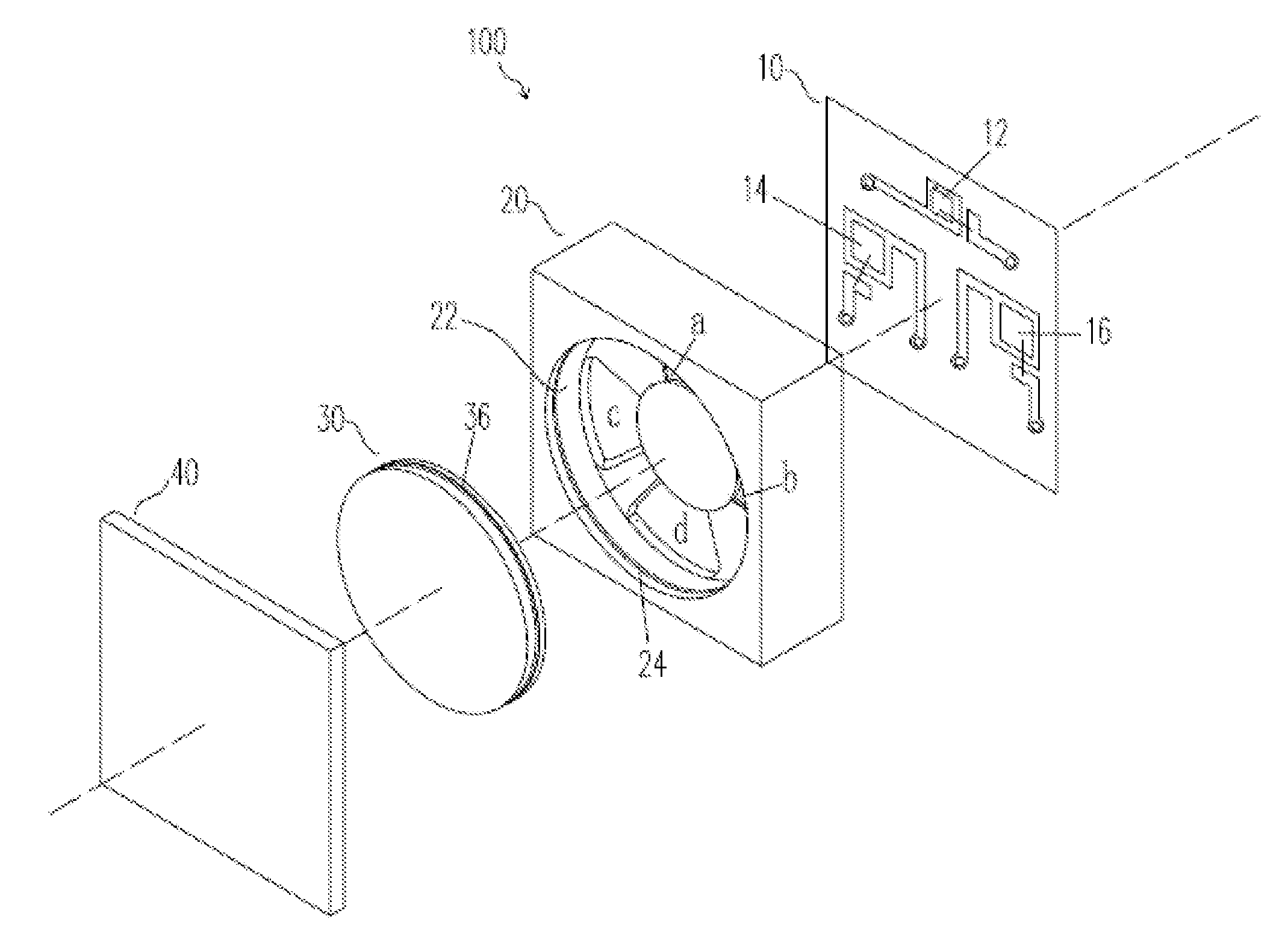
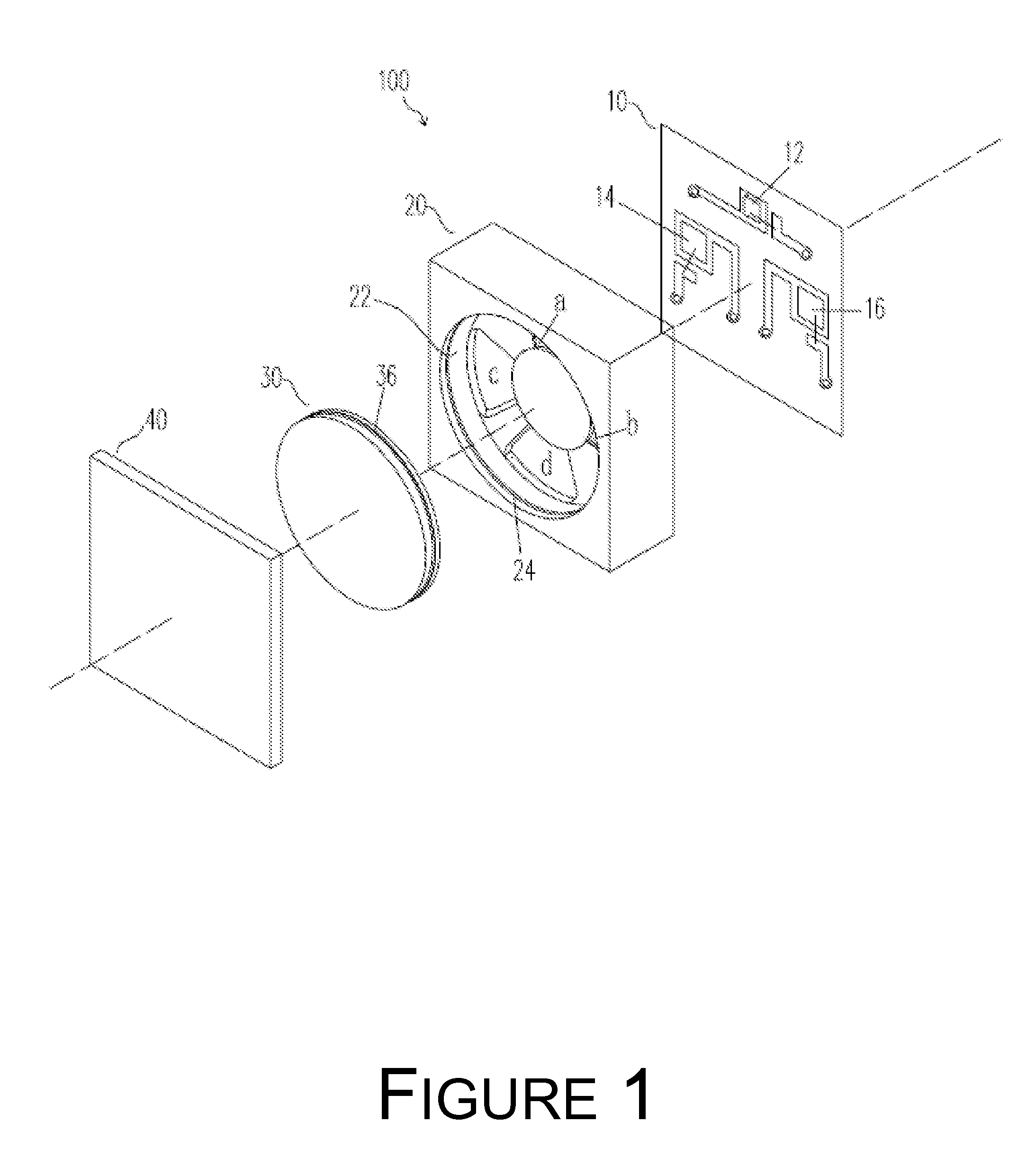
[0035]Referring to FIGS. 1 and 2, FIG. 1 illustrates a three-dimensional exploded view of a tilt sensor 100 in accordance with an embodiment of the present invention. FIG. 2 illustrates a cross-sectional view of the tilt sensor 100 in accordance with an embodiment of the present invention. The tilt sensor 100 comprises a backplane 10, a base 20, a moving component 30, and a cover 40. A light emitting component 12, a first light sensing component 14, and a second light sensing component 16 are disposed on the backplane 10. In one embodiment, the backplane 10 is a printed circuit board (PCB) or another type of circuit board. In one embodiment, the light emitting component 12 comprises an infrared light emitting diode, and each of the first and second light sensing components 14, 16 comprises a phototransistor. However, as those skilled in the art would appreciate, in other embodiments one or more of these components may be substitute with respective one or more components having simil...


PUM


Abstract

A tilt sensor capable of sensing tilt in multiple directions includes a backplane, a base, a cover, and a moving component. A light emitting component and light sensing components are disposed on the backplane. The base, disposed on the backplane, includes a recess the bottom of which having a plurality of through-holes. The through-holds expose the light emitting and light sensing components. The cover, disposed on the base, covers the recess. The moving component, disposed in the recess and between the base and the cover, includes a shelter portion where center of gravity of the moving component is located. The moving component moves in directions toward which the tilt sensor is titled, and the shelter portion covers some of the through-holes and blocks light to or from the light emitting and light sensing components. The moving component is highly sensitive and not subject to malfunction caused by friction-induced static electricity.

Description

CROSS-REFERENCE TO RELATED APPLICATION[0001]This application claims the priority benefit of Chinese Patent Application No. 201110117538.7, filed on May 6, 2011. The entirety of the above-identified patent application is hereby incorporated by reference and made a part of this specification.BACKGROUND[0002]1. Technical Field[0003]The present invention relates to tilt sensors and, more particularly, to a type of tilt sensors that can be implemented in devices such as digital cameras and notebook computers with tilt sensing applications.[0004]2. Description of Related Art[0005]Tilt sensors are nowadays widely used in devices such as digital cameras and notebook computers with tilt sensing applications. When the device is tilted to the left or right or placed upside down, a tilt sensor therein can detect a tilted state of the device.[0006]Japan Patent Application Publication No. JPA-2007139643 describes a tilt sensor that is composed of a backplane, a base, a rotating body, and a reflec...

Claims


Application Information

Patent Timeline
Patent Type & Authority Applications(United States)
IPC IPC(8): G01C9/06
CPCG01C9/14
Inventor HSIAO, HSIN-TUAN
Owner EVERLIGHT ELECTRONICS
Why Eureka
Try Eureka