
Transmission mechanism of eyebrow tattoo machine

Active Publication Date: 2012-11-08
MEI CHI HSINYEN
View PDF17 Cites 7 Cited by
  • Summary
  • Abstract
  • Description
  • Claims
  • Application Information

AI Technical Summary

Benefits of technology

[0008]In view of the aforementioned drawbacks of the transmission mechanism of the conventional eyebrow tattoo machines, the inventor of the present invention conducted extensive research and experiment and finally succeeded in developing an improved transmission mechanism for use in an eyebrow tattoo machine. The transmission mechanism disclosed herein is intended to effectively solve the plastic deformation and heat generation problems in the prior art and increase the service lives of eyebrow tattoo machines.
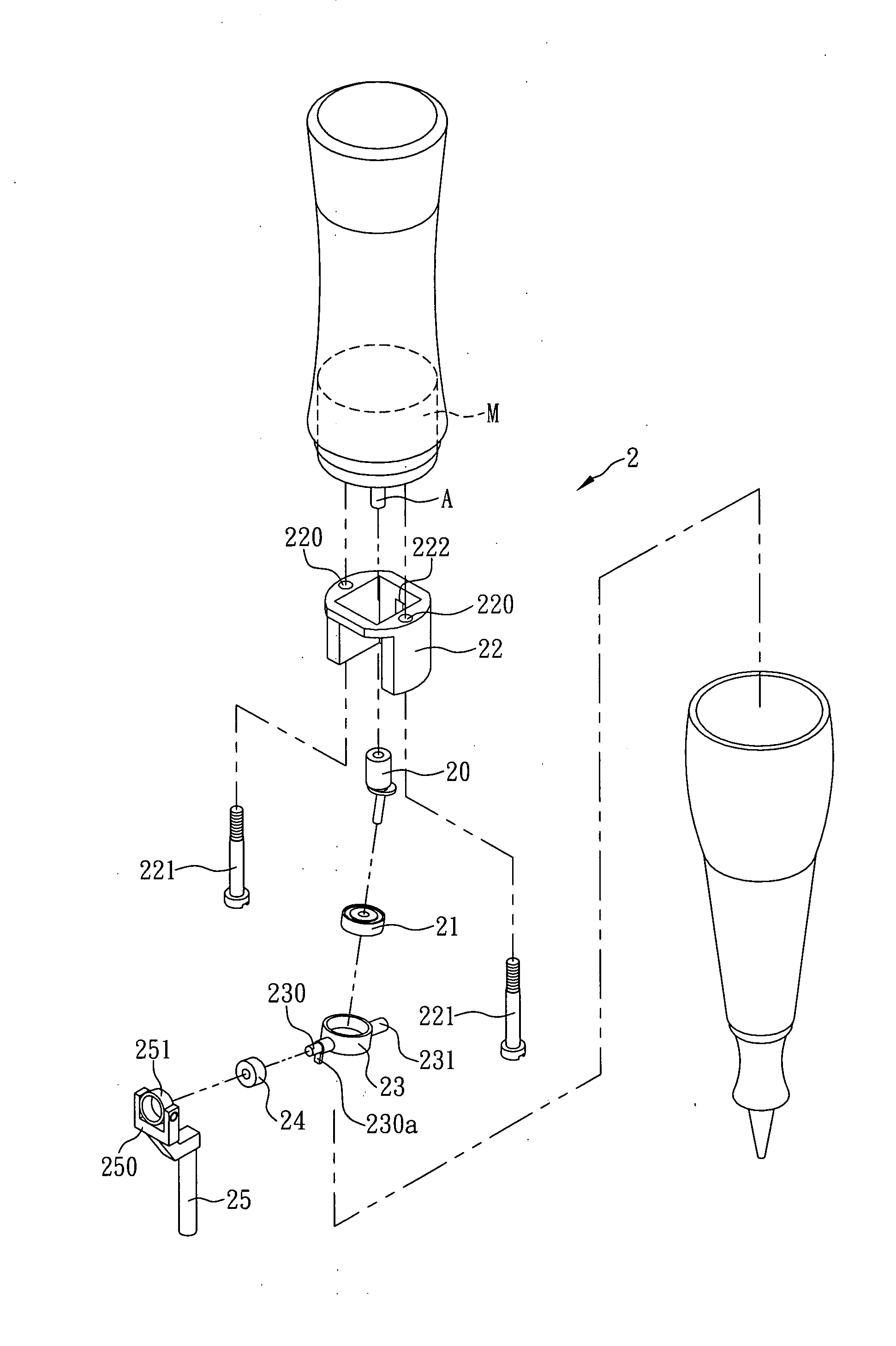
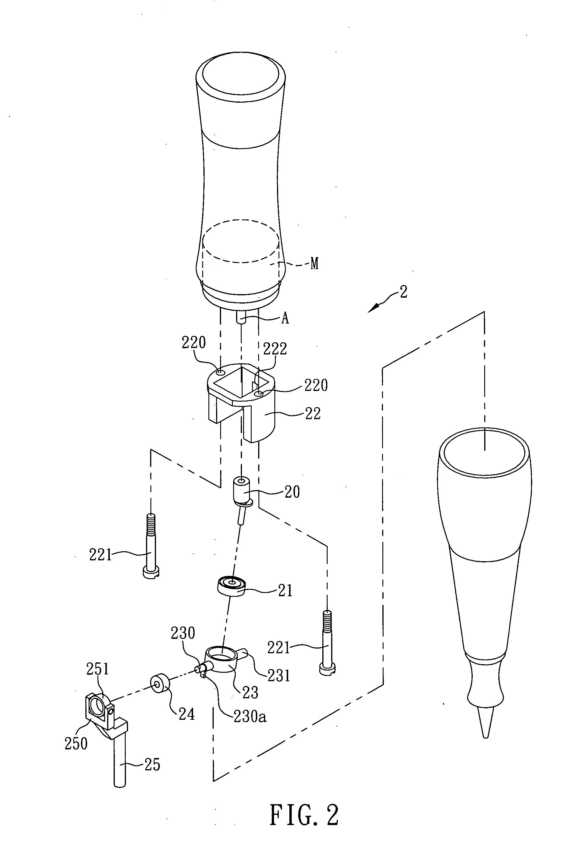
[0009]It is an object of the present invention to provide a transmission mechanism of an eyebrow tattoo machine, wherein the transmission mechanism includes an eccentric rotation shaft, an upper bearing, a position-limiting cover, a swinging rod element, a lateral bearing, and a linking member. The eccentric rotation shaft is connected to the driving axle of a motor, and the bottom end of the eccentric rotation shaft is configured to rotate eccentrically with respect to the driving axle of the motor. The inner periphery of the upper bearing is coupled with the bottom end of the eccentric rotation shaft so as for the eccentric rotation shaft to drive the upper bearing into rotation. The position-limiting cover is longitudinally provided with a position-limiting groove and is located adjacent to the eccentric rotation shaft. The swinging rod element is mounted around and fixed to the outer periphery of the upper bearing and is protrudingly provided with a swinging rod and a position-limiting rod on two sides respectively. The position-limiting rod extends into the position-limiting groove. When the eccentric rotation shaft drives the upper bearing and consequently the swinging rod element, the position-limiting rod is only allowed to swing up and down in the position-limiting groove, thus causing the end of the swinging rod that is away from the upper bearing to swing up and down. The inner periphery of the lateral bearing is coupled with the swinging rod so as for the lateral bearing to be driven to swing up and down by the swinging rod. The linking member is pivotally provided with a pivoting element. The pivoting element is mounted around and fixed to the outer periphery of the lateral bearing so that, when the lateral bearing swings up and down, the pivoting element is driven up and down by the lateral bearing and moves the linking member up an down, thereby causing a tattoo needle or tattoo needles which are connected either directly or indirectly to the linking member to move vertically up and down. Thus, according to the present invention, the upper bearing and the lateral bearing serve as the major components for power transmission, and power transmission does not involve the engaging action of plastic components. This solves the problem of deformation and loosening of the conventional plastic power transmitting components and significantly increases the service life of an eyebrow tattoo machine using the disclosed transmission mechanism.
[0010]Another object of the present invention is to provide the foregoing transmission mechanism, wherein the swinging rod is protrudingly provided with a stopper, and the lateral bearing has one side lying against the stopper to prevent unnecessary sliding of the lateral bearing.

Problems solved by technology

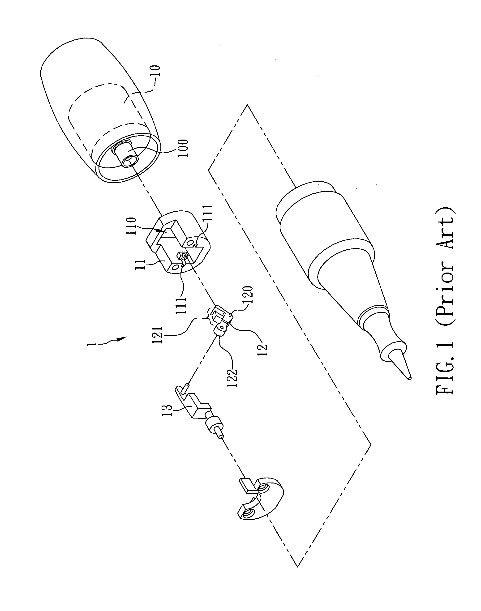
However, the conventional eyebrow tattoo machine 1 leaves much room for improvement.
Even worse, the swinging element 12 and the linking member 13 may shake in an undesirable manner, thus shortening the service life of the eyebrow tattoo machine 1 and, in the end, incurring expenses for buying a new eyebrow tattoo machine.
Moreover, when the eyebrow tattoo machine 1 is used in an area of relatively high hardness, such as where the eyebrow bone lies, the linking member 13 and the needle connected thereto may be shifted angularly and therefore lead to erroneous operation of the eyebrow tattoo machine 1.
Such erroneous operation not only compromises the efficiency of the eyebrow tattooing procedure seriously, but also may cause irremediable defects on customers' faces.
For example, friction with the metallic swinging element 12 tends to generate high heat, and the adjacent components are very likely to deteriorate after long-term exposure to such high heat.
As a result, an eyebrow tattoo machine with the metallic swinging element 12 still has a shortened service life, which translates into a monetary burden on the user.

Method used


Image

  • Transmission mechanism of eyebrow tattoo machine
  • Transmission mechanism of eyebrow tattoo machine
  • Transmission mechanism of eyebrow tattoo machine

Examples


Embodiment Construction

[0018]The inventor of the present invention has long been engaged in the research, development, and manufacture of eyebrow tattoo machines and like cosmetic products. In the process, the inventor has found that the transmission mechanism of the conventional eyebrow tattoo machines is typically configured to transmit power by the engaging action of a plastic component. This engaging action, however, often leads to deformation and loosening of the plastic component, which not only cause operational problems but also shorten the service lives of eyebrow tattoo machines. Although attempts have been made to overcome the aforesaid drawbacks of the prior art by improving the overall structure of the conventional eyebrow tattoo machines, an ideal solution has yet to be found. Therefore, the inventor came up with the idea of applying bearing transmission to the transmission mechanism of an eyebrow tattoo machine. It is hoped that, simply by improving the transmission mechanism, deformation a...


PUM


Abstract

The present invention refers to a transmission mechanism of an eyebrow tattoo machine, which includes an eccentric rotation shaft connected to a driving axle of a motor and having a bottom end configured to rotate eccentrically with respect to the driving axle, an upper bearing coupled with the bottom end of the eccentric rotation shaft, a position-limiting cover longitudinally provided with a position-limiting groove, and a swinging rod element mounted to the upper bearing and provided with a swinging rod and a position-limiting rod on two sides respectively. Since the position-limiting rod is only allowed to swing up and down in the position-limiting groove when the eccentric rotation shaft drives the upper bearing and the swinging rod element, the end of the swinging rod away from the upper bearing can swing up and down and then drive a tattoo needle to move vertically up and down through a lateral bearing.

Description

FIELD OF THE INVENTION[0001]The present invention relates to a transmission mechanism of an eyebrow tattoo machine, which utilizes an upper bearing and a lateral bearing to serve as the major components for transmitting power from a motor to a tattoo needle without getting involved engaging action of plastic components, so as to effectively solve the problem of deformation and loosening of the conventional plastic power transmitting components and significantly increases the service life of the eyebrow tattoo machine.BACKGROUND OF THE INVENTION[0002]Eyebrow tattooing is a relatively minor cosmetic procedure widely practiced nowadays. Typically, eyebrow tattooing involves the use of a motorized machine which drives a single needle or a group of needles into vertical oscillation and thereby injects a liquid dye preparation into the skin in or around the eyebrow areas, so as to form continuous patches of permanent color markings intended to enhance the appearance of eyebrows.[0003]Gene...

Claims


Application Information

Patent Timeline
IPC IPC(8): F16H21/36
CPCY10T74/18216F16H21/50A61M37/0076Y10T74/18056
Inventor LIN, SU-LIN
Owner MEI CHI HSINYEN
Learn More