Detachable power drive unit for propelling and steering manual wheelchairs

Inactive Publication Date: 2012-11-08
BRILL BRADLEY +3
View PDF2 Cites 29 Cited by
  • Summary
  • Abstract
  • Description
  • Claims
  • Application Information

AI Technical Summary

Benefits of technology

[0017]The objects of the present invention are achieved and the disadvantages of the prior art are overcome by the present invention which provides a power drive unit for manual wheelchair comprising a frame, two independently controlled drive wheels, a battery, a hitching unit for coupling the device to the wheelchair, a force transfer apparatus, a user interface and a controller. The frame, motors, batteries and wheels have a low profile which allows them to fit in the space underneath a standard manual wheelchair. The hitching unit couples the device to the wheelchair, yet allowing a fa

Problems solved by technology

These salient features come at the cost of the occupant having to propel the wheelchair by manual force or rely on external help to push the wheelchair.
One drawback of these types of embodiments is that the device is located ahead of the wheelchair, which restricts the ability of the occupant to get near stationary objects such as tables and sinks.
Another drawback concerns the low contact force between the drive wheel/s and the ground stemming from the inability of the occupant to exert down force as most of his/her weight is borne by the wheelchair wheels.
This significantly limits the traction to the ground and the ability of the device to propel the wheelchair on loose or slippery surfaces.
These patents specifically, and all others with similar architecture can only be steered by orienting the drive wheel assembly which is exceedingly difficult in the confined space undern

Method used


Image

  • Detachable power drive unit for propelling and steering manual wheelchairs
  • Detachable power drive unit for propelling and steering manual wheelchairs
  • Detachable power drive unit for propelling and steering manual wheelchairs

Examples


Embodiment Construction

[0025]An illustrative embodiment of the present invention will now be described in detail, with reference to the accompanying drawings. It should be understood that only structures considered necessary for clarifying the present invention are described herein. Other conventional structures, and those of ancillary and auxiliary components of the system, will be known and understood by those skilled in the art. Throughout the following detailed description and in the drawings, like numbers refer to like parts.

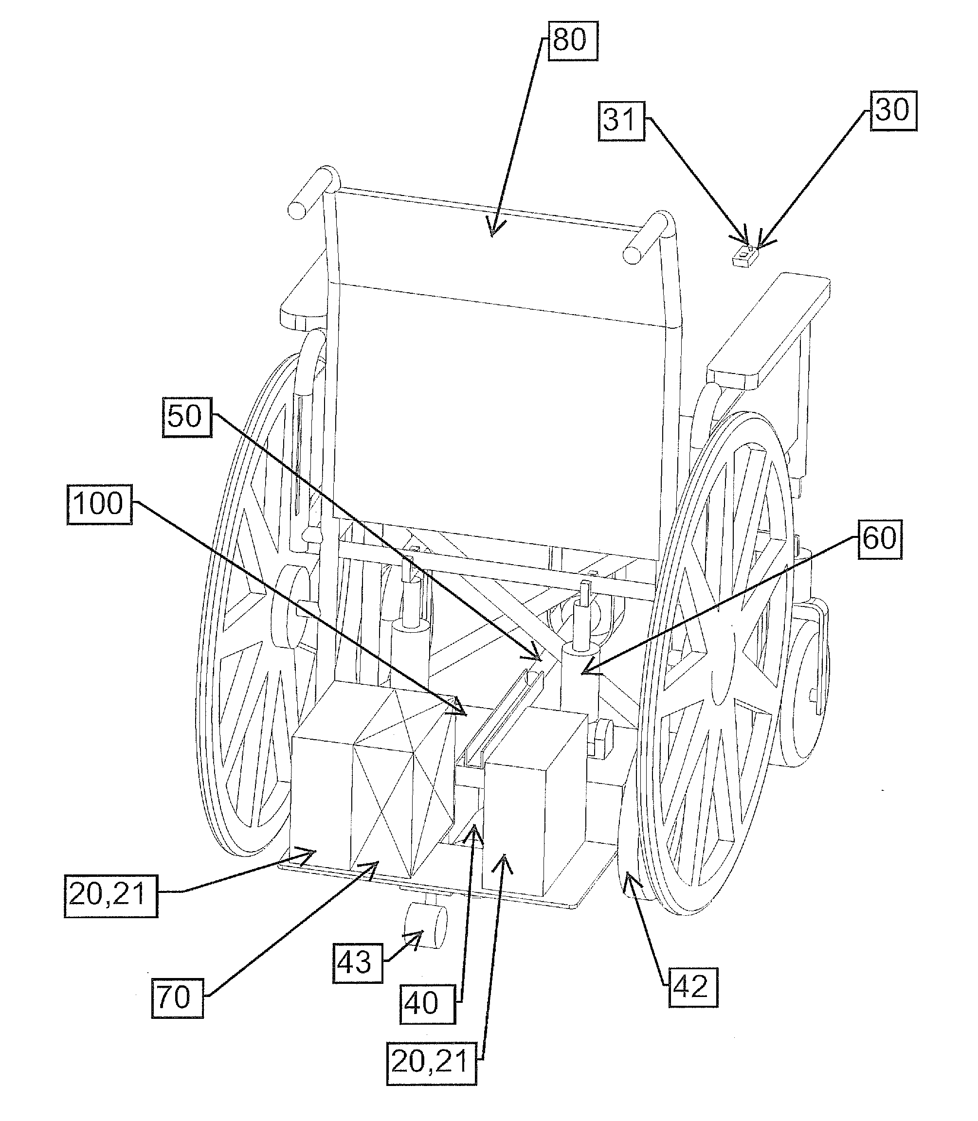
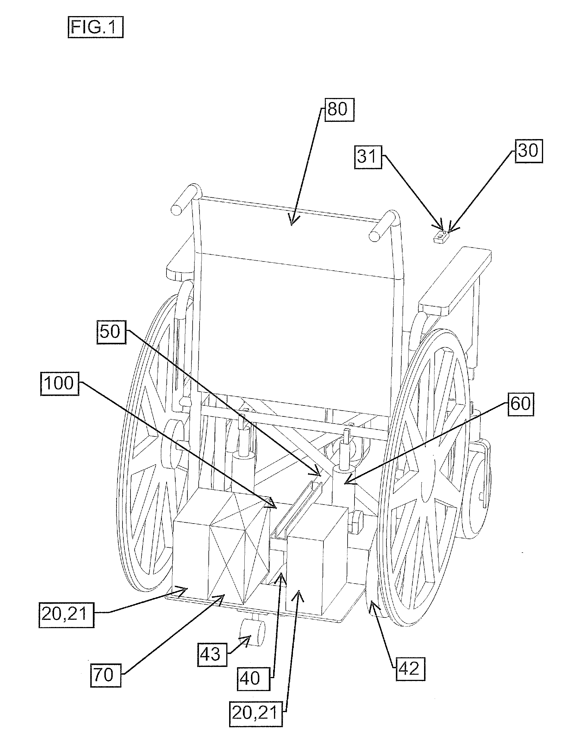
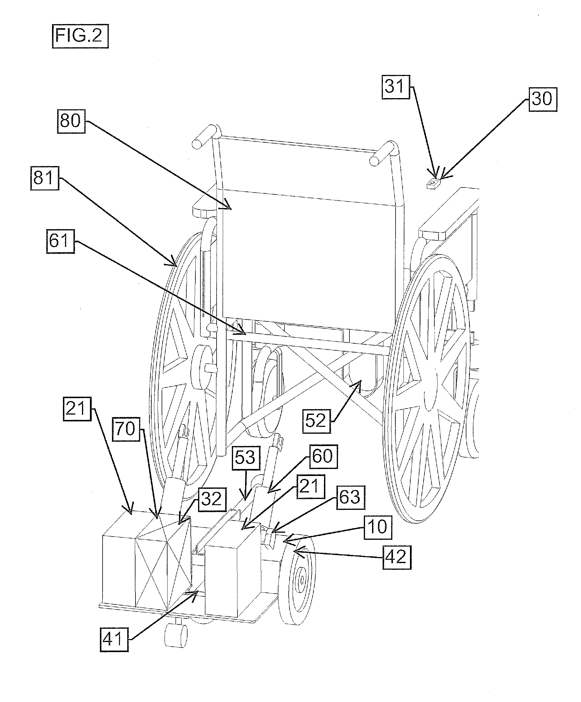
[0026]Referring now to FIGS. 1-5, there is shown a detachable power drive unit according to an illustrative embodiment of the present invention. The detachable power drive unit is generally denoted by reference numeral 100, and includes a frame 10, an electrical power unit 20, a user interface 30, a drive train 40 with two independently controlled drive wheels 42, a hitching unit 50, a force transfer apparatus 60 and a motor controller 70.

Frame 10

[0027]The frame 10 is the physica...


PUM


Abstract

A detachable power drive unit for propelling and steering a manual wheelchair is provided which comprises a frame, two independently controlled drive wheels, a power source, a hitching unit for coupling the device to the wheelchair, a force transfer apparatus, a user interface and a controller. The frame, motors, batteries and wheels have a low profile, which allows them to fit in the space underneath a standard manual wheelchair. The hitching unit couples the device to the wheelchair, yet allowing a fair degree of rotational motion to occur which minimizes the possibility of a wheel losing contact with the ground. The force transfer apparatus is a spring loaded arm that gets compressed by the wheelchair chassis during docking, thus transferring a significant portion of the wheelchair and occupant weights onto the drive wheels and ensuring adequate ground contact force and, as a consequence, drive traction.

Description

CROSS-REFERENCE TO RELATED APPLICATIONS[0001]The present application claims priority under 35 USC §119 based on U.S. Provisional Application No. 61 / 481,379 filed on May 2, 2011. The entire subject matter of this priority document is herein incorporated by reference.BACKGROUND OF THE INVENTION[0002]1. Field of the Invention[0003]The present invention relates generally to wheelchairs. More specifically, the present invention relates to a detachable, power drive unit for manual wheelchairs capable of propelling and steering said wheelchair and of being attached and detached by the wheelchair occupant without any assistance.[0004]2. Description of the Background Art[0005]There are over a million manual wheelchair users in the United States in 2010. Manual wheelchairs are designed to be comfortable, lightweight, maneuverable and can be easily folded and stowed away. These salient features come at the cost of the occupant having to propel the wheelchair by manual force or rely on external...

Claims


Application Information

Patent Timeline
IPC IPC(8): A61G5/04A61G5/02
CPCA61G5/047A61G2005/1054A61G2005/0825A61G5/1054A61G5/0825
Inventor BRILL, BRADLEYDAMPHOUSSE, ERICKLEINKE, DARRELMASDON, GALEN
Owner BRILL BRADLEY
Why Eureka
Try Eureka