Self-Injection Device with Multi-Position Cap

a self-injection device and multi-position technology, applied in the direction of infusion needles, other medical devices, infusion syringes, etc., can solve the problems of user's glucose level and the inability to give injection too far in advance, and achieve the effect of reducing the size of the self-injection devi

Active Publication Date: 2012-11-08
BECTON DICKINSON & CO
View PDF3 Cites 42 Cited by
  • Summary
  • Abstract
  • Description
  • Claims
  • Application Information

AI Technical Summary

Benefits of technology

[0010]An aspect of the present invention is to provide a self-injection device with a body and a cap that can accommodate and prote

Problems solved by technology

But the injection cannot be given too far in advance

Method used


Image

  • Self-Injection Device with Multi-Position Cap
  • Self-Injection Device with Multi-Position Cap
  • Self-Injection Device with Multi-Position Cap

Examples


Embodiment Construction

[0033]Reference will now be made in detail to embodiments of the present invention, examples of which are illustrated in the accompanying drawings, wherein like reference numerals refer to the like elements throughout. The descriptions of these embodiments exemplify the present invention by referring to the drawings.

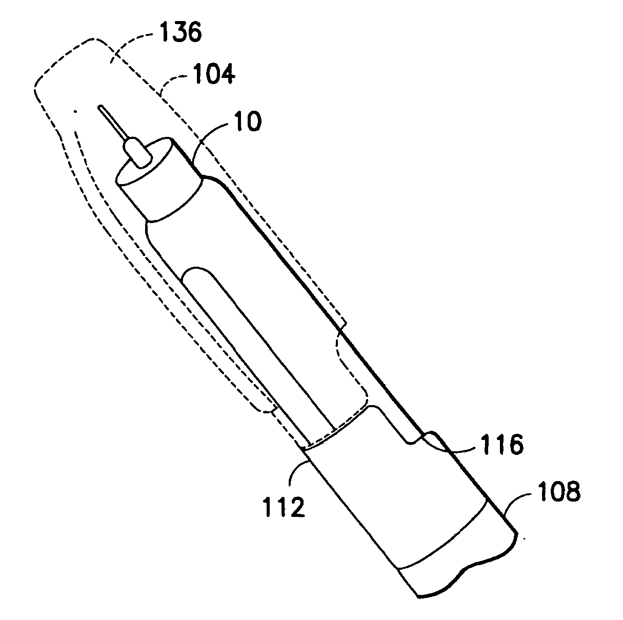
[0034]FIGS. 3 and 4 are perspective views illustrating first and second connection orientations of a self-injection device 100 in accordance with an embodiment of the present invention. As shown in FIGS. 3 and 4, the self-injection device (or pen injector) 100 includes a cap 104 and a body or pen body 108. The cap 104 and the body 108 are connectable to each other in first (for example, FIG. 3) and second (for example, FIG. 4) radial orientations. In FIG. 3, the cap 104 is connected with the body 108 in the first orientation to be as compact as possible. In other words, the overall volume and / or length of the pen injector 100 are minimized in the first orientation. In FI...


PUM


Abstract

A self-injection device (100, 200), including a pen body (108, 208) connectable to a pen needle (10), and a cap (104, 204) selectively connectable to the pen body (108, 208) in a first orientation with respect to the pen body (108, 208) to minimize the length or volume of the self injection device (100, 200), and in a second orientation to provide sufficient length or volume in an interior of the cap (104, 204) to house a pen needle (10) connected to the pen body (108, 208).

Description

CROSS-REFERENCE TO RELATED APPLICATION[0001]This application claims the benefit of U.S. Provisional Patent Application Ser. No. 61 / 266,697, filed Dec. 4, 2009 at the U.S. Patent and Trademark Office, the disclosure of which is incorporated herein by reference in its entirety.FIELD OF THE INVENTION[0002]The present invention relates generally to a self-injection device, and more particularly to self-injection device with a multi-position cap.BACKGROUND OF THE INVENTION[0003]Medication delivery pens are hypodermic syringes used for self-injection of precisely measured doses of medication. Pens are widely used, for example, by diabetics to self-inject insulin. A typical prior art medication delivery pen includes a cartridge which contains a volume of liquid medication sufficient for several doses. The dose is injected into a tissue area, such as the intramuscular tissue layer, the subcutaneous tissue layer, or the intradermal tissue layer.[0004]The assembly and operation of a typical p...

Claims


Application Information

Patent Timeline
IPC IPC(8): A61M5/32
CPCA61M5/24A61M5/31525A61M5/31533A61M2005/3104A61M5/3213A61M2005/2407A61M5/3134A61M5/3202
Inventor CRONENBERG, RICHARDJETER, RUANE
Owner BECTON DICKINSON & CO
Why Eureka
Try Eureka