
Meniscus repair

Active Publication Date: 2012-11-08
CETERIX ORTHOPAEDICS
View PDF21 Cites 64 Cited by
  • Summary
  • Abstract
  • Description
  • Claims
  • Application Information

AI Technical Summary

Benefits of technology

[0038]The various devices described herein may address and / or solve problems and challenges faced by other meniscus suture or repair devices. In particular, the devices described herein are configured to fit adjacent (and in some cases over, around or alongside) the meniscus, including one or both of the femoral face and / or tibial face of the meniscus. Thus, the devices described herein may include a narrow distal end region and / or distal shaft region allowing positioning within the narrow confines of the meniscal space. This improvement in geometry may be achieved by reducing the size and / or thickness of the arms. For example, in variations adapted for use with a suture element configured as a suture shuttle that docks on one or more positions on the suture passer, the suture passer may include shuttle docks that are narrow or flatter, allowing the arm on which the shuttle dock is present to be narrow. In some variations the shuttle dock is oriented to minimize the height of the arm. In some variations, the tissue penetrator and / or shuttle and / or shuttle dock may be adapted to minimize the space needed for the shuttle dock, and therefore the thickness of the arm.
[0042]Part III describes meniscus suture passers that include one or more curved tissue penetrator (e.g., needle) extending from a first arm, configured to pass through the tissue and end up back at the same arm, where the suture may be secured. In some variations the device includes only a single arm from which the tissue penetrator extends and retracts, passing the suturing element (suture, suture shuttle, pullwire / loop, etc). In some variations the device includes a second arm or other deflector surface which helps guide or direct the tissue penetrator back through the tissue to a second location (e.g. proximal or distal to the starting location of the tissue penetrator). In some variations, the device includes a telescoping tissue penetrator that extends through the tissue with a telescoping (or over- or under-sliding element, as in a two-part construction) element.

Problems solved by technology

Further, in any of these methods, the suture passer may approach the meniscus from the anterior of the knee, and may approach the meniscus tear from the apex of the meniscus.

Method used


Image

  • Meniscus repair
  • Meniscus repair
  • Meniscus repair

Examples


Embodiment Construction

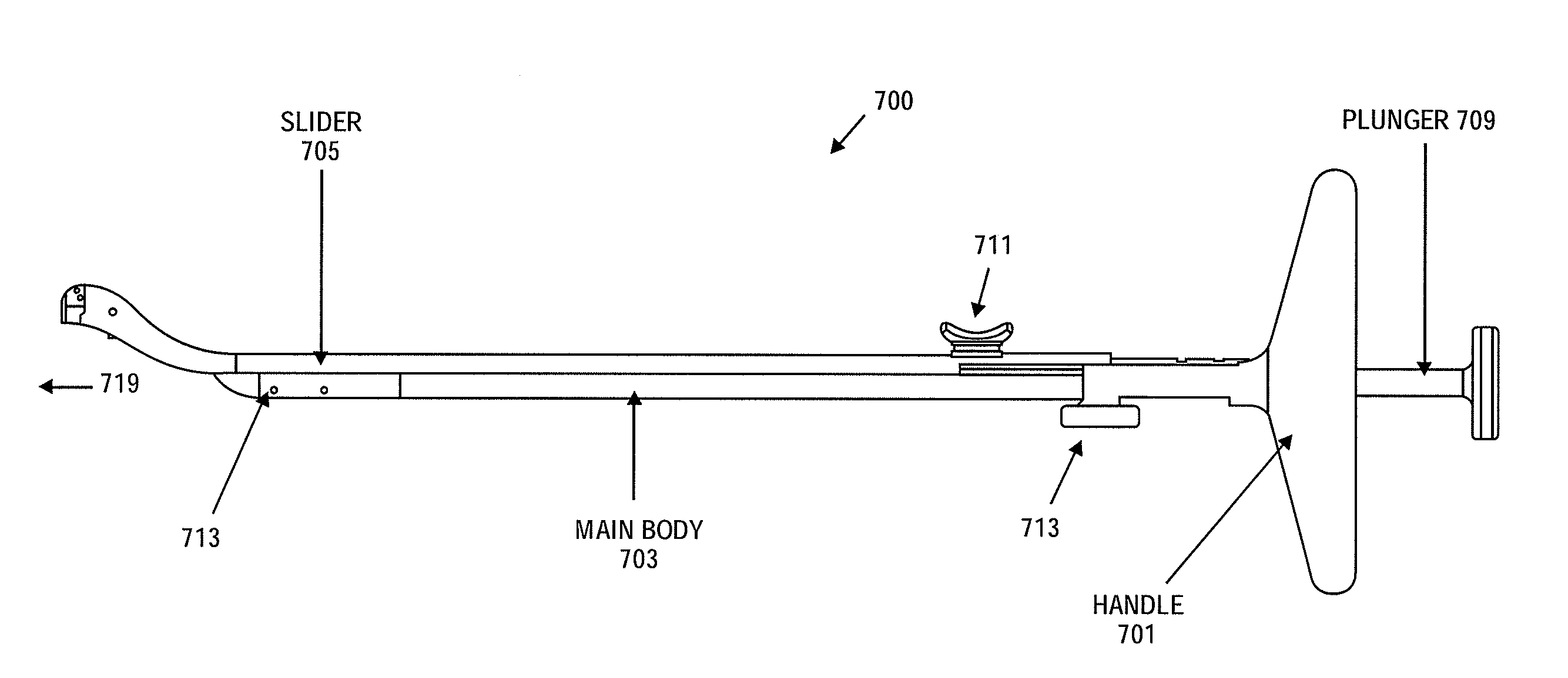
[0129]Described herein are suture passers for meniscus repair. In general, these devices may be referred to herein as meniscus repair suture passers, meniscus repair devices, or simply suture passers. The devices described herein may be configured to repair a meniscus (knee joint meniscus), and have a distal end region that has two arms, at least one of which is extendable and retractable distally / proximally along the longitudinal axis of the device (e.g., “longitudinally). The device has a deployed configuration with a distal-facing opening configured to fit around the tapering outer surfaces (e.g., the superior and inferior surfaces) of a meniscus. The device also has an insertion configuration in which one arm (e.g., the bent or angled arm) extends distally beyond the other arm of the device. One or more additional operational configurations may be formed intermediate to these two positions, and the device may be switched between these configurations by retracting or extending on...


PUM


Abstract

Methods for repairing a meniscus, and particularly a torn meniscus. A method of repairing a meniscus may include using a suture passer to pass a suturing element from the region between the superior surface of the meniscus and the femoral condyle, through the meniscus tissue, into the region between the inferior surface of the meniscus and the tibial plateau, across the inferior surface of the meniscus, and back to the superior surface of the meniscus, without deeply penetrating the posterior capsular region of the knee. Equivalently, the suture element may be passed from the inferior surface of the meniscus to the superior surface and back to the inferior surface.

Description

CROSS REFERENCE TO RELATED APPLICATIONS[0001]This patent application claims the benefit of priority to the following provisional patent applications: U.S. Provisional Patent Application No. 61 / 483,200, titled “Meniscus Repair” and filed May 6, 2011, and U.S. Provisional Patent Application No. 61 / 511,922, titled “Meniscus Repair” and filed Jul. 26, 2011.[0002]This patent application may be related to U.S. patent application Ser. No. 12 / 942,803, filed on Nov. 9, 2010, titled “DEVICES, SYSTEMS AND METHODS FOR MENISCUS REPAIR” which claim priority to U.S. Provisional Patent Application Nos. 61 / 259,572, filed Nov. 9, 2009, titled “DEVICES, SYSTEMS AND METHODS FOR MENISCUS REPAIR”; 61 / 295,354, filed Jan. 15, 2010, titled “DEVICES, SYSTEMS AND METHODS FOR MENISCUS REPAIR”; and 61 / 318,215, filed Mar. 26, 2010, titled “CONTINUOUS SUTURE PASSERS HAVING TISSUE PENETRATING SUTURE SHUTTLES”.[0003]All of these applications are herein incorporated by reference in their entiretyINCORPORATION BY REF...

Claims


Application Information

Patent Timeline
Patent Type & Authority Applications(United States)
IPC IPC(8): A61B17/062A61B17/34A61B17/04
CPCA61B17/0469A61B17/0482A61B17/0485A61B17/062A61B17/0625A61B2017/2927A61B2017/0496A61B2017/06009A61B2017/06014A61B2017/06042A61B2017/06176A61B2017/0472A61B17/11A61B17/04
Inventor SALIMAN, JUSTIN D.CULBERT, BRAD S.JASSO, ALEXANDERHENDRICKSEN, MICHAEL J.MCCUTCHEON, JOHN G.BENDER, CHRIS P.MURILLO, MICHAEL
Owner CETERIX ORTHOPAEDICS
Learn More