
Compostng apparatus and method

Inactive Publication Date: 2012-11-15
GREAT WALL OF CHINA WASTE
View PDF7 Cites 15 Cited by
  • Summary
  • Abstract
  • Description
  • Claims
  • Application Information

AI Technical Summary

Benefits of technology

[0007]Another feature of the present invention is to provide a compositing apparatus which is compact, easy to use and empty, economical to construct, requires very little maintenance and which can compost soft and hard organic materials.
[0010]Another feature of the present invention is to provide a composting apparatus which is totally integrated and which is transportable and can be moved to different sites.

Problems solved by technology

Such horizontal drum composters are known in the art but these known composters have several disadvantages in that many of these utilize screens to divide the drum into sub-composting compartments and the drums are oriented at an angle whereby the compost material can move from an inlet end to an outlet end during rotation of the drum.
For the material to move through the compartments, it needs to decompose to pass through the screens and often the inlet end of the drum will clog up with material which backs up to the inlet end for the reason that the decomposition has not sufficiently taken place and cannot pass through the screens and backs up.
The material also clogs the screens and requires constant servicing to unclog.
Accordingly, these composters have not proven to be efficient.
Again, drum constructions have been found to be expensive to construct and require constant maintenance and repair due to sieve malfunction.
The cost of transporting and disposing large volumes of organic waste has escalated in recent years due to increase in labour cost and transportation costs.
Such organic waste also is not put to valuable use such as for the fertilization of soil whereby to be recycled into nature.
When organic waste is used as landfills, it is slowly decomposted and if such is buried while being contained in plastic bags, the decomposition will take much longer and contamination results due to the use of plastics material.

Method used


Image

  • Compostng apparatus and method
  • Compostng apparatus and method
  • Compostng apparatus and method

Examples


Embodiment Construction

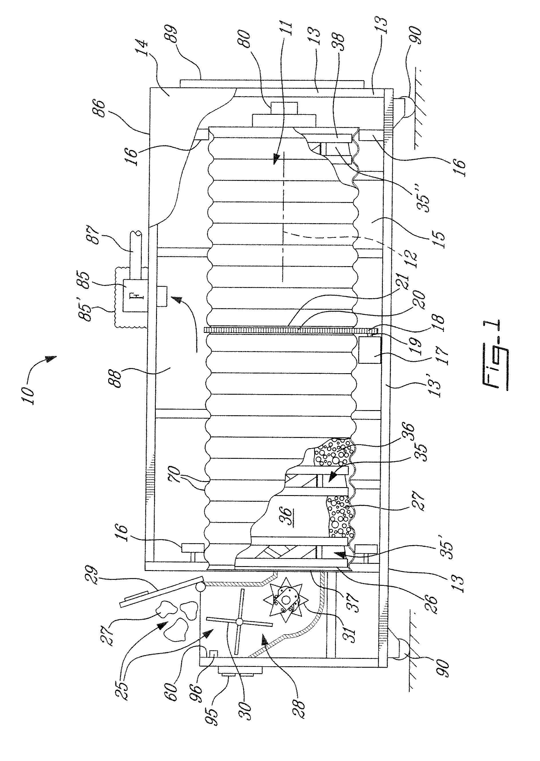
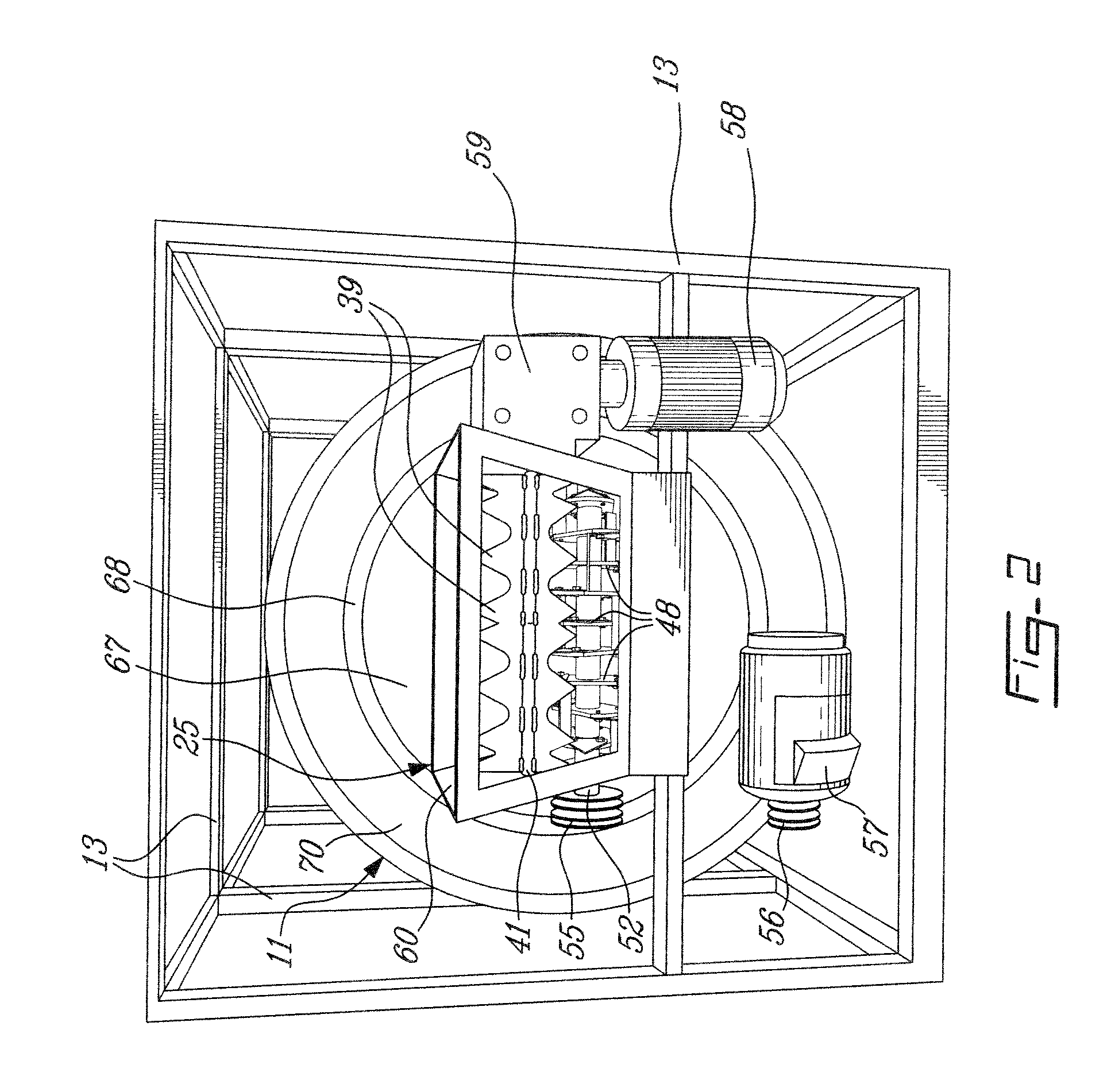
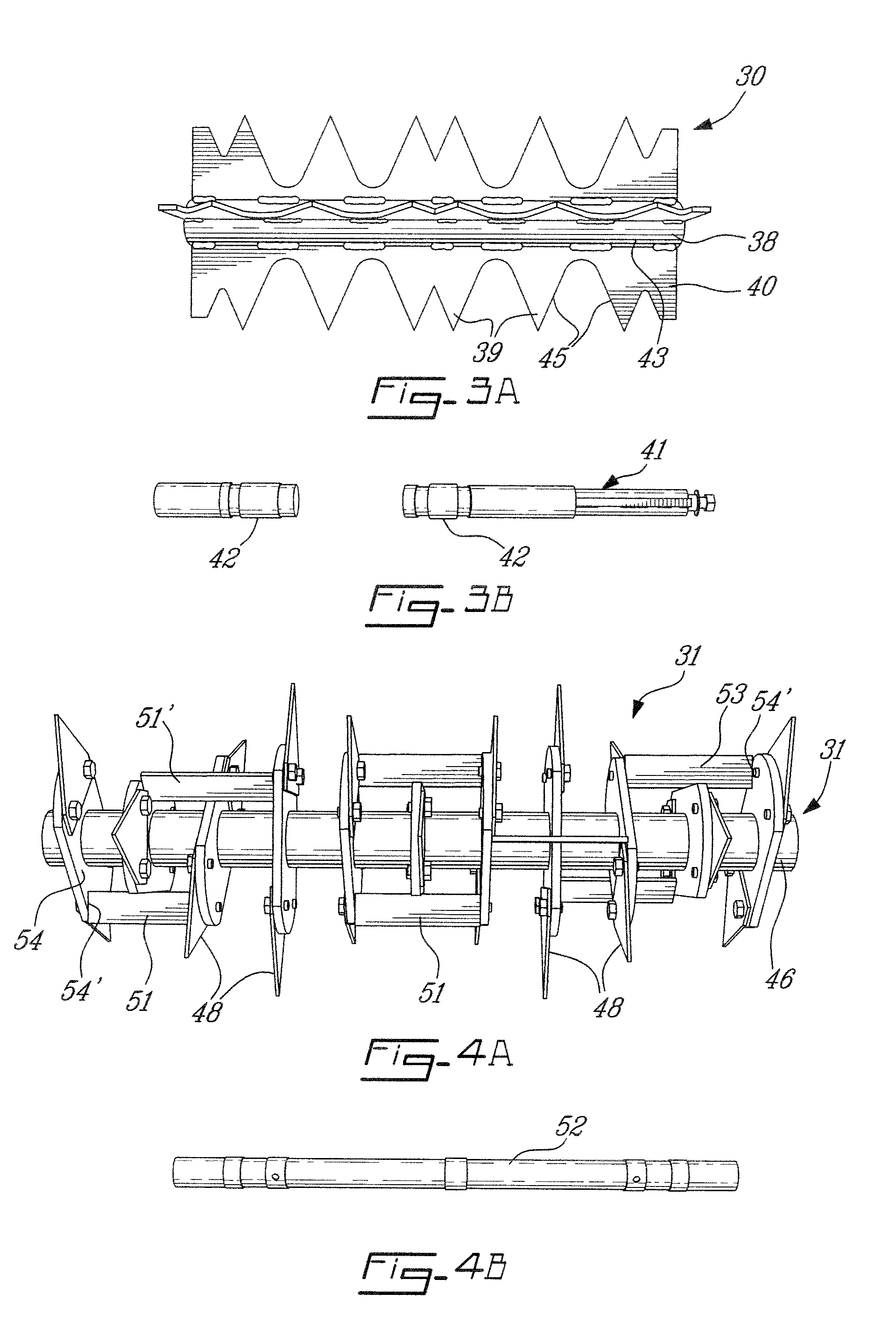
[0029]Referring now to the drawings and more particularly to FIG. 1, there is shown generally at 10 the composting apparatus of the present invention. The composting apparatus 10 comprises a cylindrical drum 11 rotatably supported along a central axis 12 thereof within a frame 13 which is provided with panels 14 to enclose the cylindrical drum 11. The panels 14 are removable from the frame 13 for access to the apparatus. The drum is rotatably and horizontally supported by large support rollers 15 secured to the bottom frame members 13′ and guide wheels 16 disposed on both sides of the drum at the bottom and top of the drum. A drive motor 17 has a drive sprocket 18 secured to a drive shaft 19 thereof. The drive sprocket 18 is coupled to a drive link chain 20 which is in toothed engagement with a drive sprocket ring 21 secured about the drum. The drive sprocket ring 21 is illustrated in FIG. 10 and as hereinshown it consists of ring straps 22 provided with spaced-apart teeth sections ...


PUM


Abstract

A composting apparatus and method is described. The apparatus comprises a cylindrical drum which is horizontally rotatably supported. A hopper is disposed at a feed end of the drum for receiving organic waste material in soft or hard form. A material shredding mechanism and a grinding mechanism are rotatably secured in the hopper and driven in counter-rotation for shredding and grinding the organic waste material and feeding it into an inlet opening of the drum. A series of material mixing and conveying vane assemblies are secured spaced-apart inside the drum and define sub-composting compartments therebetween. The material mixing and conveying vane assemblies have a plurality of vanes secured in spaced-apart relationship and project interiorly towards a central longitudinal axis of the drum and are oriented at a common angle to mix, further shred and displace shredded and ground material from the inlet opening towards the rear discharge end of the drum. The gases escaping from the drum are vented from an enclosure of the composting apparatus and the material inside the drum is discharged by suction.

Description

TECHNICAL FIELD[0001]The present invention relates to a composting apparatus and method for the degradation of organic waste in soft or hard form.BACKGROUND ART[0002]The present invention utilizes a horizontal rotating drum in which organic waste material in hard or soft form is shredded and ground in a hopper before being introduced in an inlet opening of the drum which is constantly in rotation. Oxygen in the air surroundings of the drum is introduced therein through the hopper during normal use of the composter apparatus and surrounding air in an enclosure for the composter is exhausted. Such horizontal drum composters are known in the art but these known composters have several disadvantages in that many of these utilize screens to divide the drum into sub-composting compartments and the drums are oriented at an angle whereby the compost material can move from an inlet end to an outlet end during rotation of the drum. For the material to move through the compartments, it needs t...

Claims


Application Information

Patent Timeline
IPC IPC(8): C05F11/08C12M1/10
CPCC05F17/0223C12M3/00C12M1/10C12M1/00Y02P20/145C05F17/929Y02W30/40
Inventor BASSILE, ELIAS
Owner GREAT WALL OF CHINA WASTE
Learn More