Current Threshold Response Mode for Arc Management

a threshold response and arc technology, applied in the field ofplasma processing, can solve problems such as damage to the substrate or the chamber, arc mitigation via power diversion, and defects in the substrate, and achieve the effect of reducing the voltage and reducing the voltag

Active Publication Date: 2012-11-15
AES GLOBAL HLDG PTE LTD
View PDF4 Cites 17 Cited by
  • Summary
  • Abstract
  • Description
  • Claims
  • Application Information

AI Technical Summary

Problems solved by technology

Electrical arcs can sometimes form within a plasma processing chamber and cause damage to the substrate or the chamber or can deposit particles that cause defects in a substrate.
Thus, arc mitigation via power diversion reduces processing efficiency and throughput.
Yet, shunt time cannot be too short since arcs can flare back up or spawn new arcs if power returns before the arc is sufficiently extinguished.
Yet, by fixing the shunt time according to the slowest arc decay rate, power is often shunted longer than necessary for arcs that quickly decay.

Method used


Image

  • Current Threshold Response Mode for Arc Management
  • Current Threshold Response Mode for Arc Management
  • Current Threshold Response Mode for Arc Management

Examples


Embodiment Construction

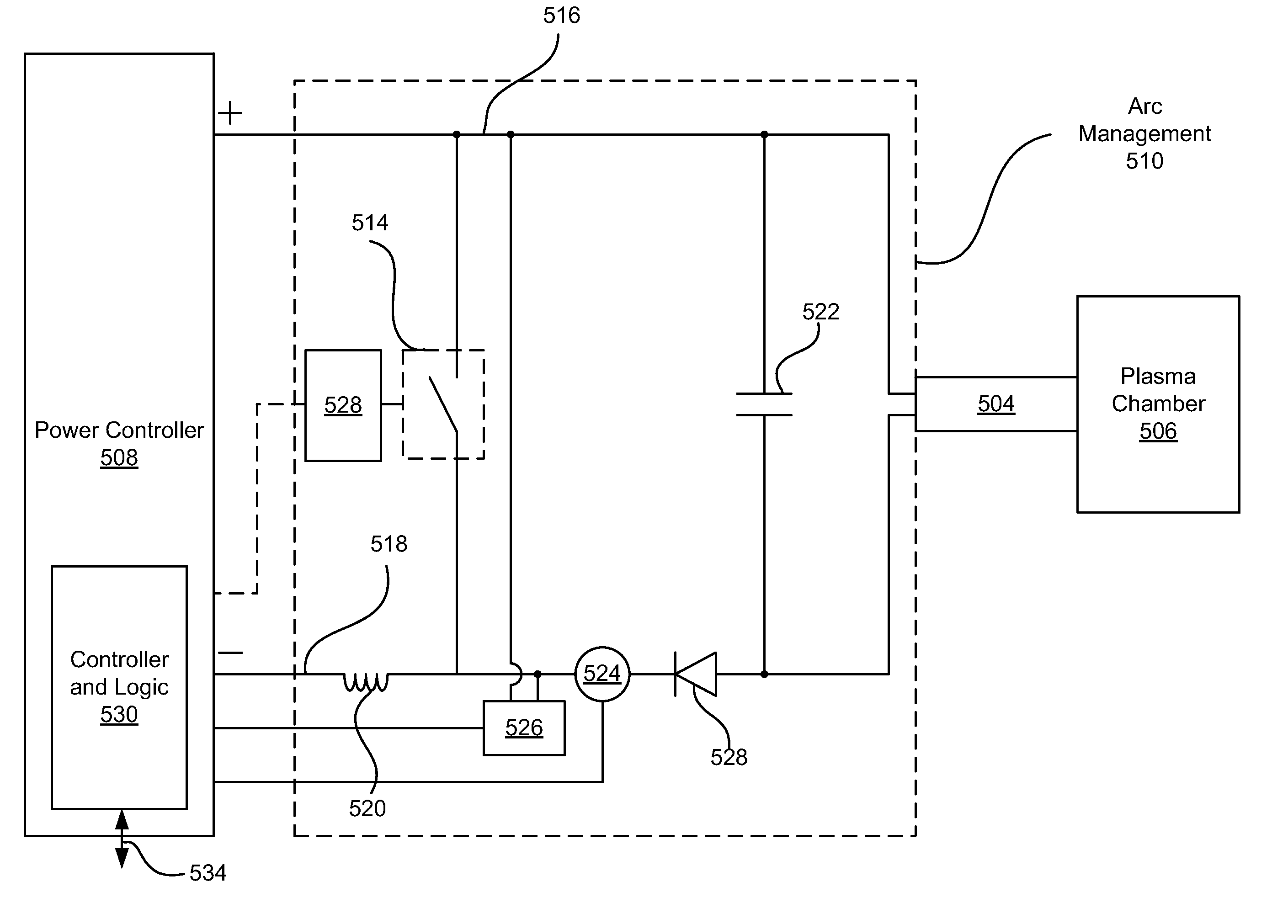
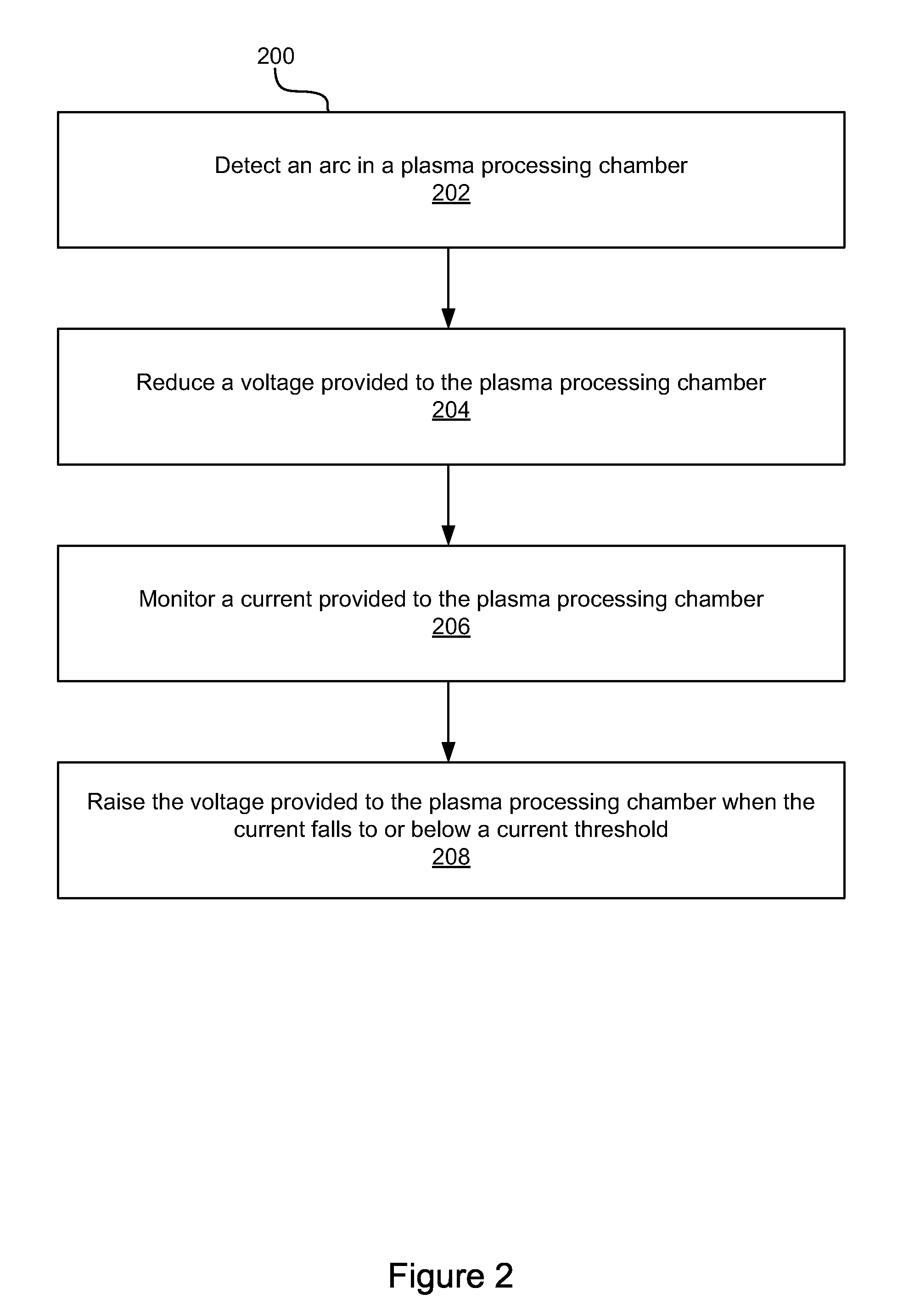
[0012]Rather than allow the slowest arc decay rate to dictate a shunt period, this disclosure describes systems, methods, and apparatuses for mitigating arcs tailored to the decay rate of individual arcs. Instead of shunting for a fixed period of time, shunting ends when the current provided to the plasma chamber has fallen to a level that can be considered safe for power resumption without risk of arc flare up.

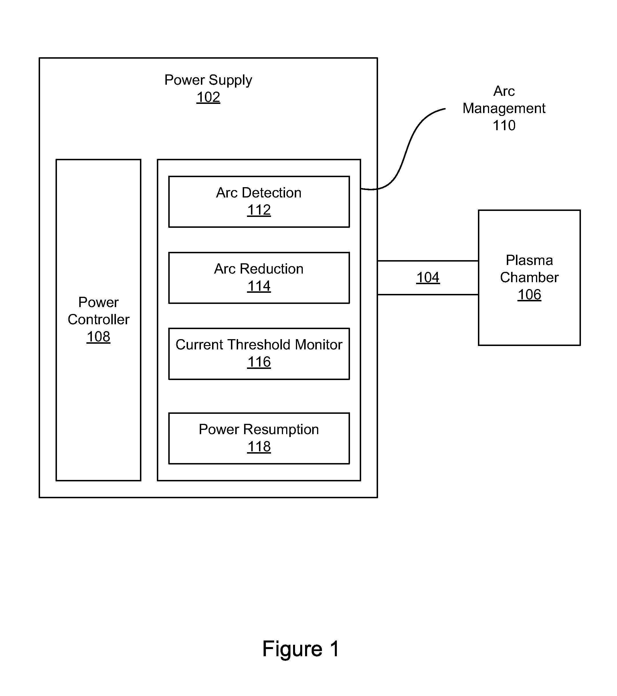
[0013]FIG. 1 illustrates an arc management portion 110 of a power supply 102 providing power to a plasma chamber 106 via a cable 104. The power supply 102 powers electrodes within the plasma chamber 106, via power controller 108, in order to ignite and sustain a plasma, and where the power has a steady state voltage and a steady state current. The power controller 108 can be a DC power supply, including switching components (e.g., MOSFET, FET, IGBT, etc.) and control logic for applying DC power pulses to the plasma chamber 106, where the pulses may be applied to multiple cath...


PUM

PropertyMeasurementUnit
voltageaaaaaaaaaa
voltageaaaaaaaaaa
voltageaaaaaaaaaa

Abstract

This disclosure describes systems, methods, and apparatuses for extinguishing electrical arcs in a plasma processing chamber. Once an arc is detected, the steady state voltage provided to the plasma processing chamber can be reduced, and the current being provided to the chamber decays below a steady state value as the arc is extinguished. When the current falls to or below a current threshold, the voltage can be ramped back up bringing the voltage and current back to steady state values. This technique enables power to return to a steady state level faster than traditional arc mitigation techniques.

Description

FIELD OF THE INVENTION[0001]The present invention relates generally to plasma processing. In particular, but not by way of limitation, the present invention relates to systems, methods and apparatuses for mitigating arcs in a plasma processing chamber.BACKGROUND OF THE INVENTION[0002]Electrical arcs can sometimes form within a plasma processing chamber and cause damage to the substrate or the chamber or can deposit particles that cause defects in a substrate. Mitigation techniques often involve shunting power away from the chamber until an arc is extinguished. While power is diverted from the chamber processing efficiency decreases, and thus quickly returning the power level to steady state is desired. At the same time, the plasma, chamber, and other elements cool while power is diverted, and thus processing efficiency does not return to steady state until these temperatures return to steady state. Thus, arc mitigation via power diversion reduces processing efficiency and throughput...

Claims


Application Information

Patent Timeline
Patent Type & Authority Applications(United States)
IPC IPC(8): H05B31/26H01L21/3065
CPCH01J37/3299H01J37/32944H01J37/32064
Inventor LARSON, SKIP B.NAUMAN, KENNETH E.
Owner AES GLOBAL HLDG PTE LTD
Why Eureka
Try Eureka