Vapor chamber with improved sealed opening

a technology of vapor chamber and sealing opening, which is applied in the field of heat pipes, can solve the problems of limiting affecting the operation of vapor chambers, and affecting the operation of indirect heat exchangers, etc., so as to improve the availability of vapor chambers, reduce manufacturing costs and processes, and increase the effect of availability

Inactive Publication Date: 2012-11-15
CELSIA TECH TAIWAN INC
View PDF39 Cites 27 Cited by
  • Summary
  • Abstract
  • Description
  • Claims
  • Application Information

AI Technical Summary

Benefits of technology

[0009]An advantage of the invention is to provide an option of the second cutting, which may increase availability of vapor chambers. Besides, the manufacturing cost and process can also be reduced and simplified, respectively.

Problems solved by technology

When a vapor chamber is installed in an electronic apparatus, the protrudent filling / degassing tube usually interferes with other components or mechanisms.
This may limit availability of vapor chambers.
Further, the protrudent filling / degassing tube tends to be damaged by unexpected collisions or pressure when assembling.

Method used


Image

  • Vapor chamber with improved sealed opening
  • Vapor chamber with improved sealed opening
  • Vapor chamber with improved sealed opening

Examples


Embodiment Construction

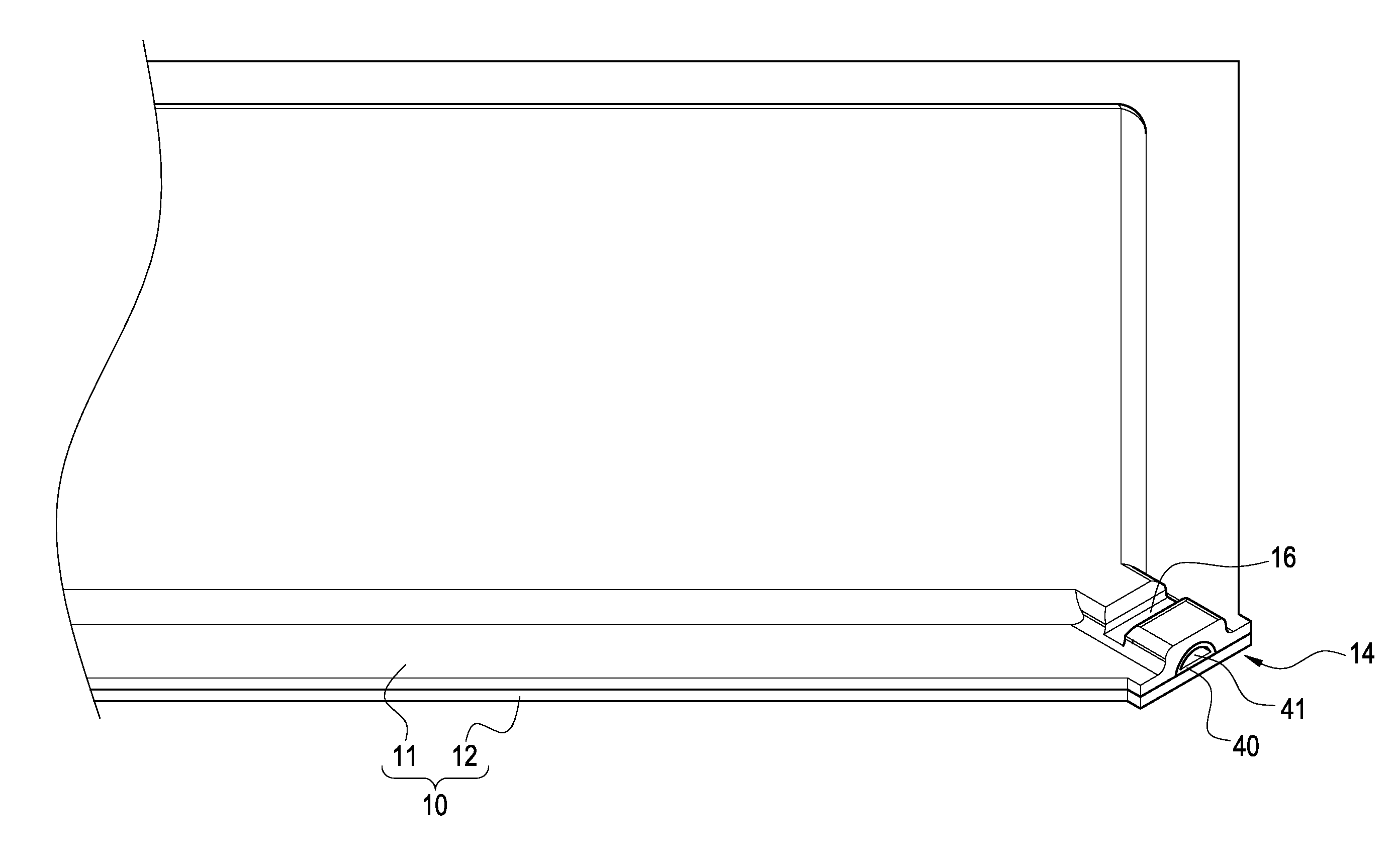
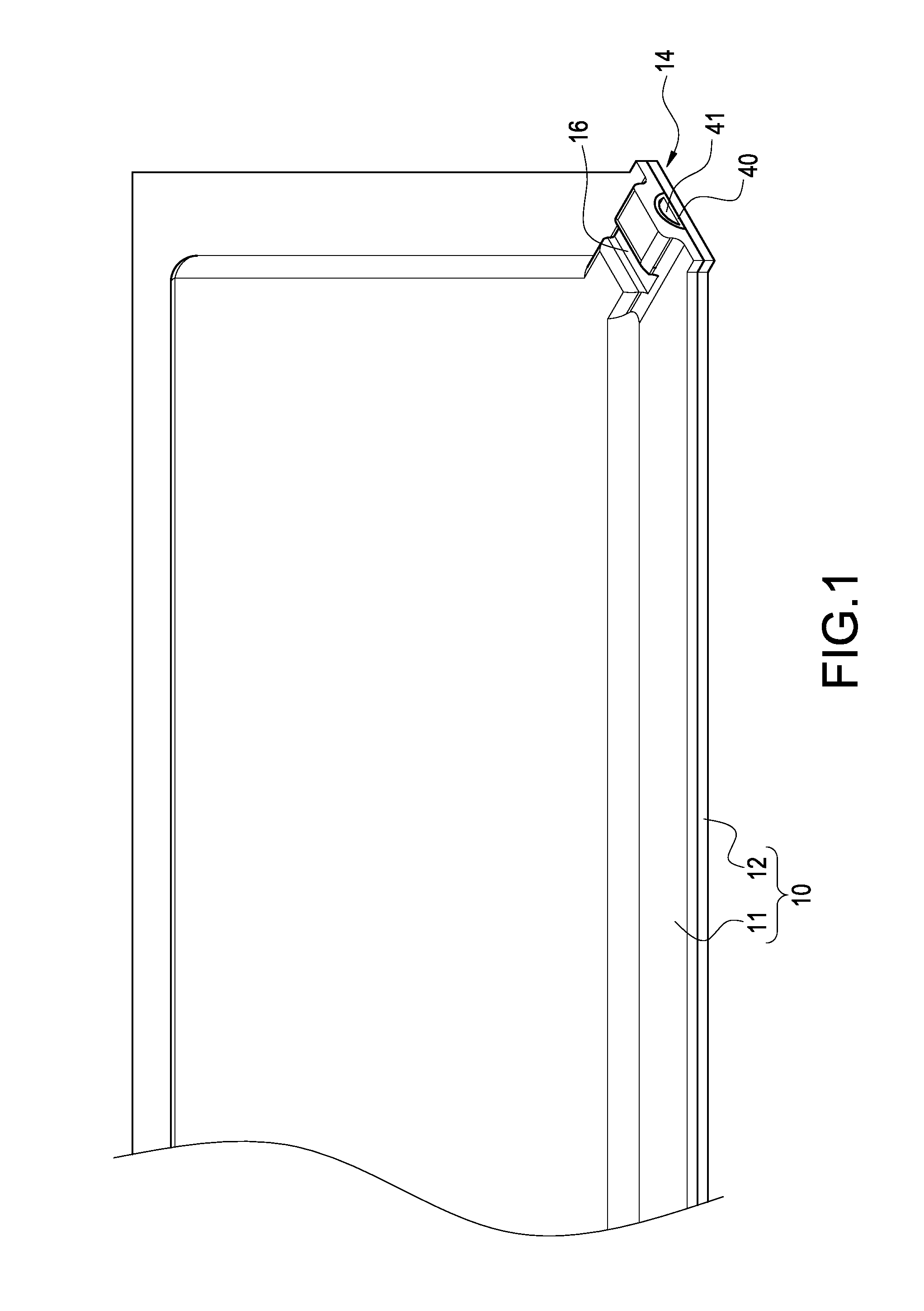
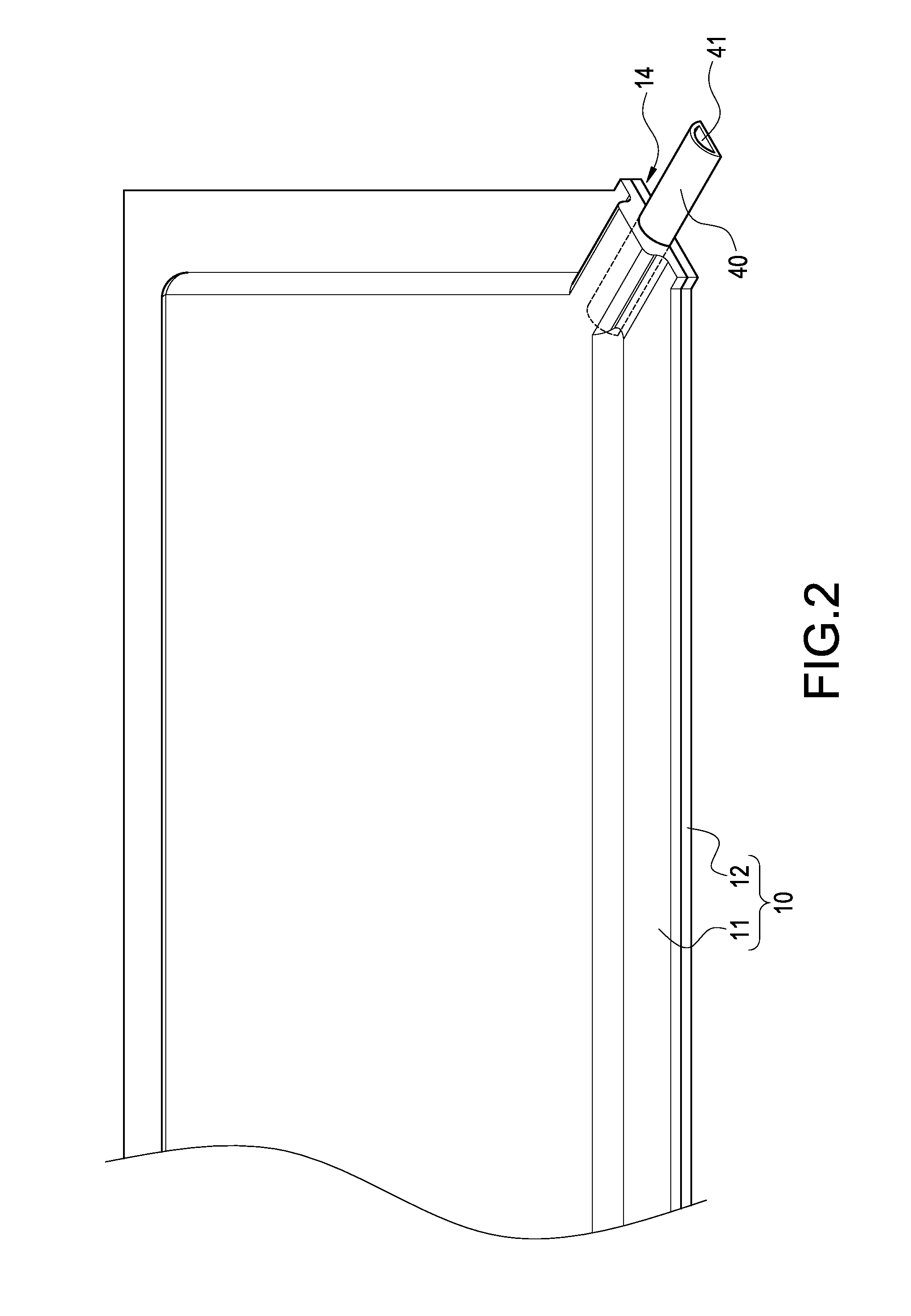
[0017]Please refer to FIG. 1. The vapor chamber of the invention includes a casing 10, a wick structure 20, a working fluid 30 and a filling / degassing tube 40.

[0018]The casing 10 is made of copper or copper alloy. In this embodiment, the casing 10 is composed of an upper plate 11 and a lower plate 12. Each of the two plates 11,12 is of a substantially rectangular shape. A periphery of the overlapping plates 11,12 is sealed by welding to form a chamber 13 therein. An angle of the casing 10 is formed with a truncated angle 14. The upper plate 11 is arced at the truncated angle 14 to form an insert channel 15 which communicates with the chamber 13.

[0019]The wick structure 20 may be metal mesh, fiber bundle or sintered metal powder. It is attached on the plates 11,12 in the chamber 13. The wick structure 20 provides a capillary force to make liquid working fluid 30 flow back.

[0020]The work fluid 30 may be water and is filled in the chamber 13. Under a room temperature, the work fluid 30...


PUM


Abstract

The vapor chamber includes a casing, wick structure, working fluid and filling/degassing tube. The casing is composed of two plates and has a chamber therein. The wick structure and working fluid are disposed in the chamber. The filling/degassing tube is connected with the casing to form a passage communicating with the chamber. A portion of the plates which overlaps the filling/degassing tube is pressed to deform for making the passage closed. And the outer end of the filling/degassing tube is flush with the side of the casing.

Description

BACKGROUND OF THE INVENTION[0001]1. Technical Field[0002]The invention relates to heat pipes, particularly to vapor chambers.[0003]2. Related Art[0004]Vapor chambers are a variant type of heat pipe. Because of lightness and thinness, vapor chambers are widely applied in portable electronic apparatuses.[0005]A conventional vapor chamber includes a casing, wick structure, working fluid and filling / degassing tube. The casing has a chamber therein. The wick structure and working fluid are disposed in the chamber. The filling / degassing tube is connected with the casing and protrudent from the chamber. The filling / degassing tube is used for filling the working fluid into the casing and degassing the air in the casing. After that, the filling / degassing tube have to be sealed by welding.[0006]When a vapor chamber is installed in an electronic apparatus, the protrudent filling / degassing tube usually interferes with other components or mechanisms. This may limit availability of vapor chambers...

Claims


Application Information

Patent Timeline
Patent Type & Authority Applications(United States)
IPC IPC(8): F28D15/04
CPCF28D15/0283F28D15/04
Inventor MEYER, IV, GEORGE ANTHONYSUN, CHIEN-HUNGCHEN, CHIEH-PINGHSIEH, MING-KUEICHIN, TE-HSUAN
Owner CELSIA TECH TAIWAN INC
Why Eureka
Try Eureka