Rotary electric machine and method for manufacturing stator used therein

a technology of electric machines and stators, which is applied in the direction of dynamo-electric machines, electrical equipment, dynamo-electric components, etc., and can solve problems such as insulation failur

Inactive Publication Date: 2012-11-15
MITSUBISHI ELECTRIC CORP
View PDF1 Cites 54 Cited by
  • Summary
  • Abstract
  • Description
  • Claims
  • Application Information

AI Technical Summary

Benefits of technology

[0009]According to the present invention, because the concentrated winding coils are configured by winding a conductor wire a predetermined number of times around the teeth so as to pass through a concave space that is formed by the trunk portions and the pairs of guide portions ...

Problems solved by technology

Thus, the concentrated winding coil is prevented from moving due to vibration, and dis...

Method used


Image

  • Rotary electric machine and method for manufacturing stator used therein
  • Rotary electric machine and method for manufacturing stator used therein
  • Rotary electric machine and method for manufacturing stator used therein

Examples


embodiment 1

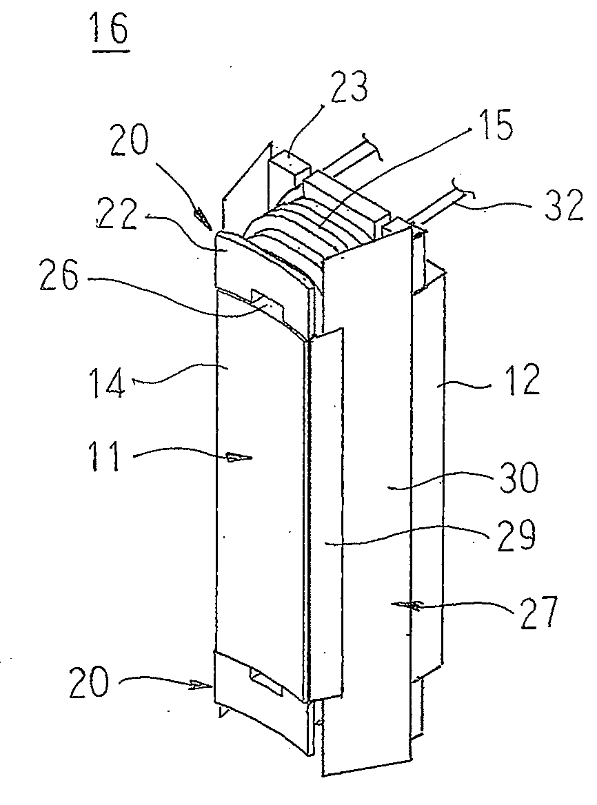
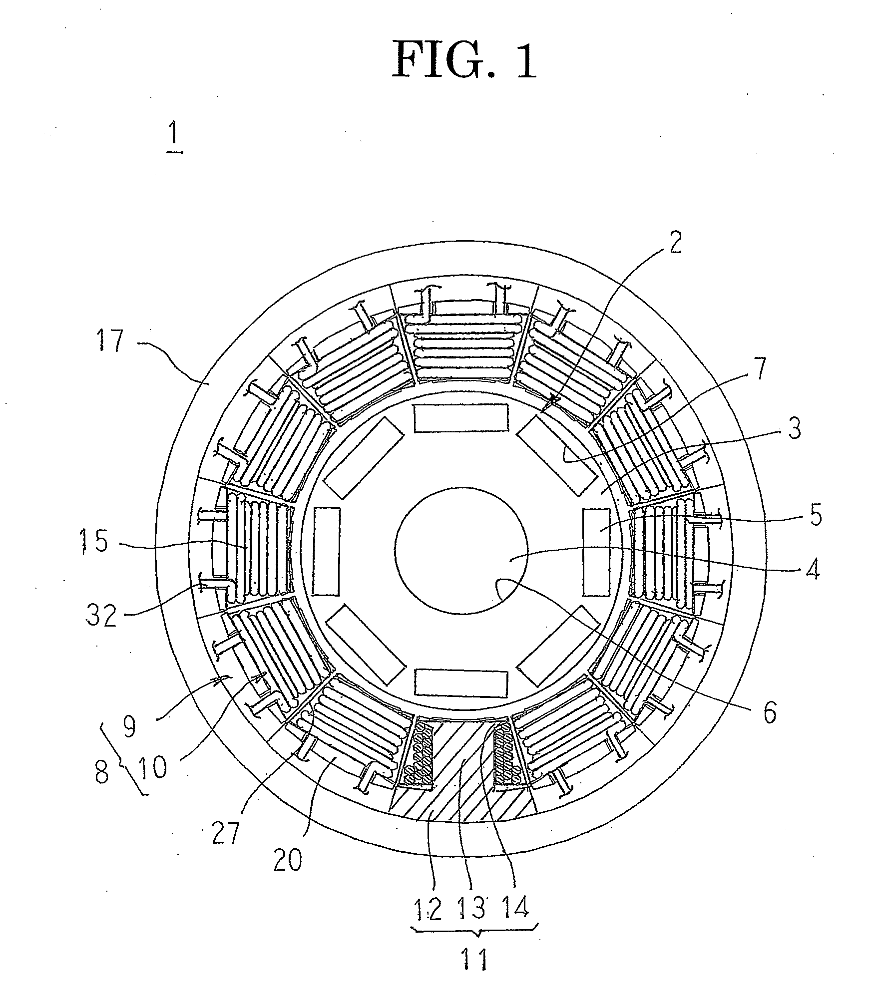
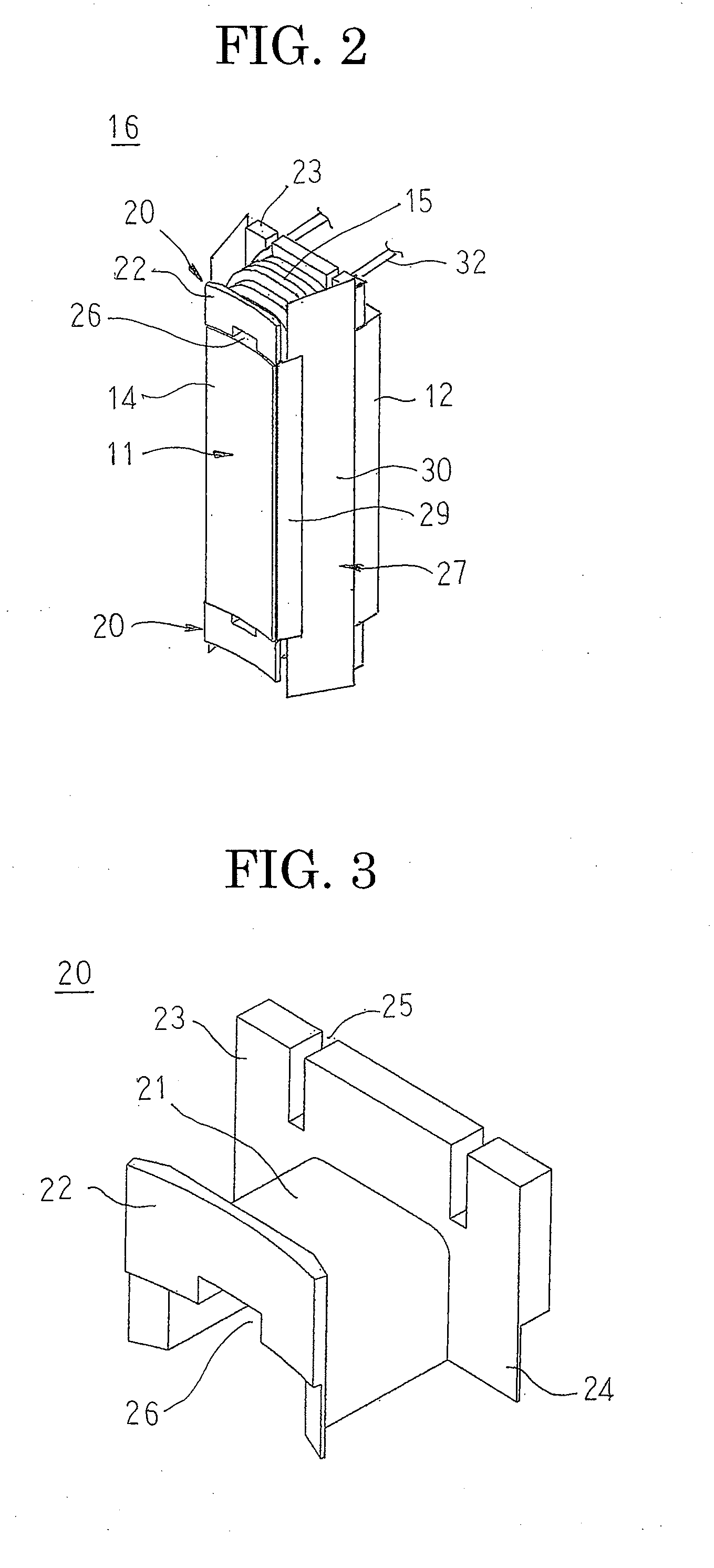
[0027]FIG. 1 is a partially cut away end elevation that shows an automotive electric motor according to Embodiment 1 of the present invention, FIG. 2 is a perspective that shows a coil assembly in the automotive electric motor according to Embodiment 1 of the present invention, FIG. 3 is a perspective that shows a bobbin that is installed in the coil assembly in the automotive electric motor according to Embodiment 1 of the present invention, FIG. 4 is a perspective that shows a core assembly in the automotive electric motor according to Embodiment 1 of the present invention, FIG. 5 is an exploded perspective that shows the core assembly in the automotive electric motor according to Embodiment 1 of the present invention, FIG. 6 is a perspective that shows the coil assembly in the automotive electric motor according to Embodiment 1 of the present invention in a state in which cover portions are not folded over, FIG. 7 is a side elevation that explains a method for winding a coil onto...

embodiment 2

[0052]FIG. 10 is a perspective that shows a bobbin that is installed in a coil assembly in an automotive electric motor according to Embodiment 2 of the present invention, FIG. 11 is a perspective that shows a core assembly in the automotive electric motor according to Embodiment 2 of the present invention, and FIG. 12 is a partially cutaway front elevation that shows a mounted state of a tension supporting arm on the core assembly in the automotive electric motor according to Embodiment 2 of the present invention.

[0053]In FIGS. 10 and 11, a tension supporting arm insertion groove 26A that functions as a tension supporting arm insertion portion is formed so as to extend from a first longitudinal end to a second end centrally in a width direction of an upper surface of a trunk portion 21 of a bobbin 20A so as to have a groove shape that has a rectangular cross section. A core assembly 31A is assembled using the bobbin 20A instead of the bobbin 20.

[0054]Moreover, the rest of the confi...

embodiment 3

[0059]FIG. 13 is a perspective that shows a mounted state of a tension supporting arm on a bobbin in an automotive electric motor according to Embodiment 3 of the present invention.

[0060]In FIG. 13, guiding grooves 33 are grooves that position a conductor wire 32 that is wound on, and a plurality thereof are formed at a predetermined pitch in a longitudinal direction on a surface of a tension supporting arm 43A that contacts the conductor wire 32 so as to have a groove direction that is inclined by a predetermined angle relative to a direction that is perpendicular to the longitudinal direction.

[0061]Moreover, the rest of the configuration is configured in a similar manner to Embodiment 2 above.

[0062]In Embodiment 3, although not shown, a conductor wire 32 that is led in through the first slit 25 and between the first guide portion 22 and the second guide portion 23 is guided by the guiding grooves 33 and wound around the tooth 13 and the pair of trunk portions 21 that are disposed ...


PUM

PropertyMeasurementUnit
Forceaaaaaaaaaa

Abstract

The rotary electric machine includes a rotor, and a stator including an stator core that is formed by laminating and integrating magnetic steel plates, and concentrated winding coils that are mounted to respective teeth, the stator being disposed so as to surround the rotor. Bobbins each including a trunk portion and first and second guide portions that are disposed so as to protrude from two longitudinal ends of an upper surface of the trunk portion are disposed so as to place bottom surfaces of the trunk portions alongside two axial end surfaces of the teeth. The concentrated winding coils are configured by winding a conductor wire a predetermined number of times around the teeth so as to pass through a concave space that is formed by the trunk portions and the first and second guide portions at two axial ends of the teeth.

Description

BACKGROUND OF THE INVENTION[0001]1. Field of the Invention[0002]The present invention relates to a rotary electric machine that is used in an automotive electric motor, etc., that is mounted to an automobile, for example, and to a method for manufacturing a stator that is used therein.[0003]2. Description of the Related Art[0004]In conventional stators, coils are mounted onto respective magnetic poles by disposing winding jigs alongside two axial end surfaces of the magnetic poles, winding a wire material around the magnetic poles and the winding jigs, and then pulling the winding jigs out from between the magnetic poles and the wire material (see Patent Literature 1, for example).[0005]Patent Literature 1: Japanese Patent Laid-Open No. 2004-328894 (Gazette)[0006]In conventional stators, because the coils are formed by winding the wire material around the magnetic poles and the winding jigs and then pulling the winding jigs out from between the magnetic poles and the wire material, ...

Claims


Application Information

Patent Timeline
IPC IPC(8): H02K3/38H02K15/02
CPCH02K2203/12Y10T29/49078Y10T29/49073H02K1/148H02K3/522Y10T29/49009
Inventor TSUIKI, HIRONORIKARATA, YUKINOBUYOSHIDA, SHINICHIROAKITA, HIROYUKIINOUE, MASAYA
Owner MITSUBISHI ELECTRIC CORP
Why Eureka
Try Eureka