Charger

a charger and charging current technology, applied in the field of chargers, can solve the problems of relatively low charging current and relatively low charging speed of relative high voltage, and achieve the effects of reducing costs, simple construction and low cos

Active Publication Date: 2012-11-15
FDK CORP
View PDF2 Cites 65 Cited by
  • Summary
  • Abstract
  • Description
  • Claims
  • Application Information

AI Technical Summary

Benefits of technology

[0011]When there is no difference in the voltages of all the batteries, all the batteries are charged at constant current by using the charging path without a current limiting resistor (second charging path), which equalizes the charging currents of the batteries. All the batteries can therefore be fully charged at a time and reach a state of full charge in a minimum time. It is thus possible to fully charge all the battery banks in a minimum time without causing overcharge.
[0012]The charge control just uniformly switches the charging paths according to whether there is difference in the voltages of the batteries. This reduces costs because there is no need for a complicate charge control procedure, and the charging circuit has a very simple construction.
[0013]Accordingly, the invention provides the operation and advantages of materializing at low costs the charger capable of fully charging all battery banks without causing overcharge.

Problems solved by technology

In result, the batteries having relatively high voltages are relatively low in charging current, and thus are charged at relatively low speed.

Method used


Image

  • Charger
  • Charger
  • Charger

Examples


Embodiment Construction

[0018]An embodiment of the invention will be described below with reference to the attached drawings.

Configuration of Charger

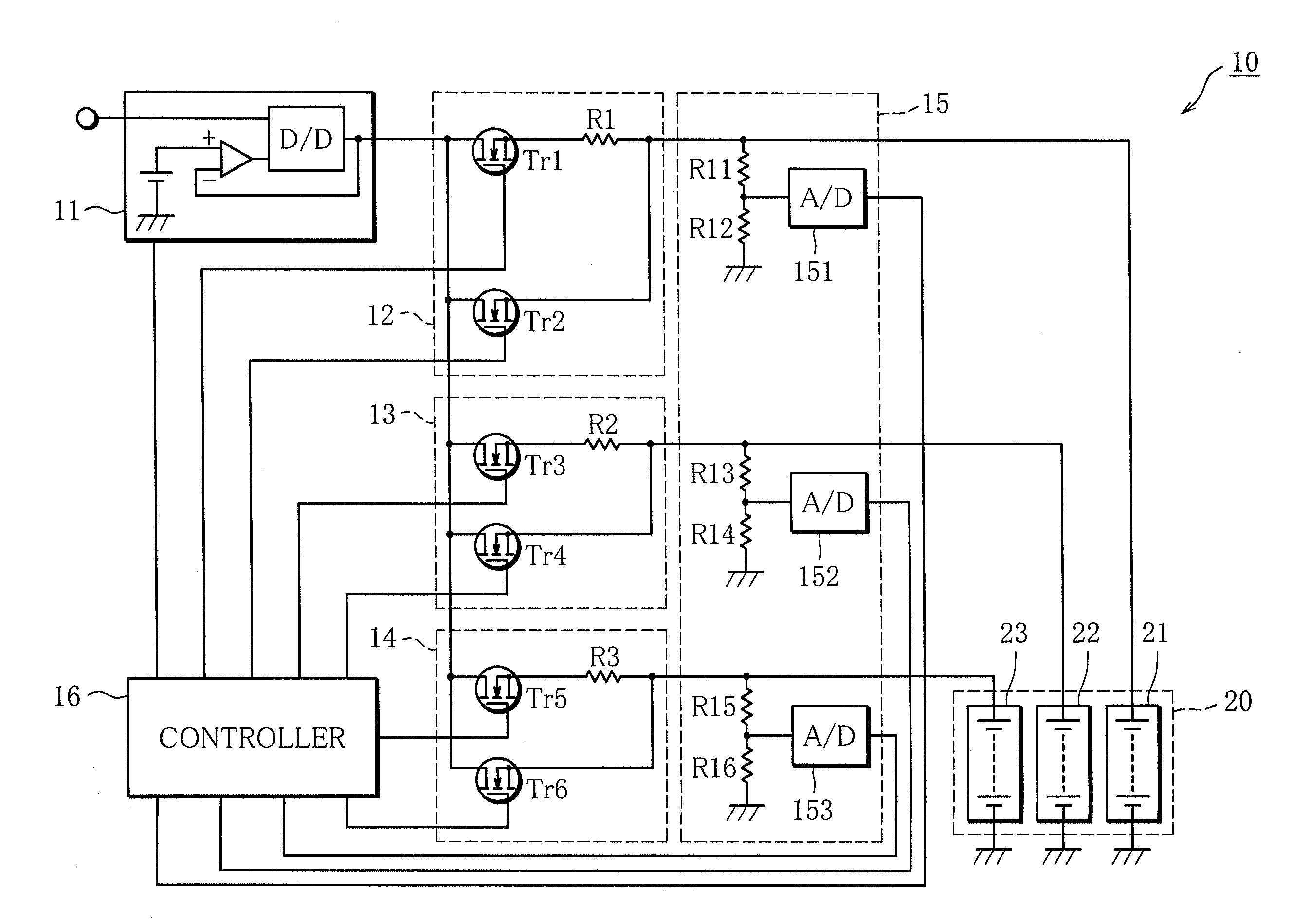
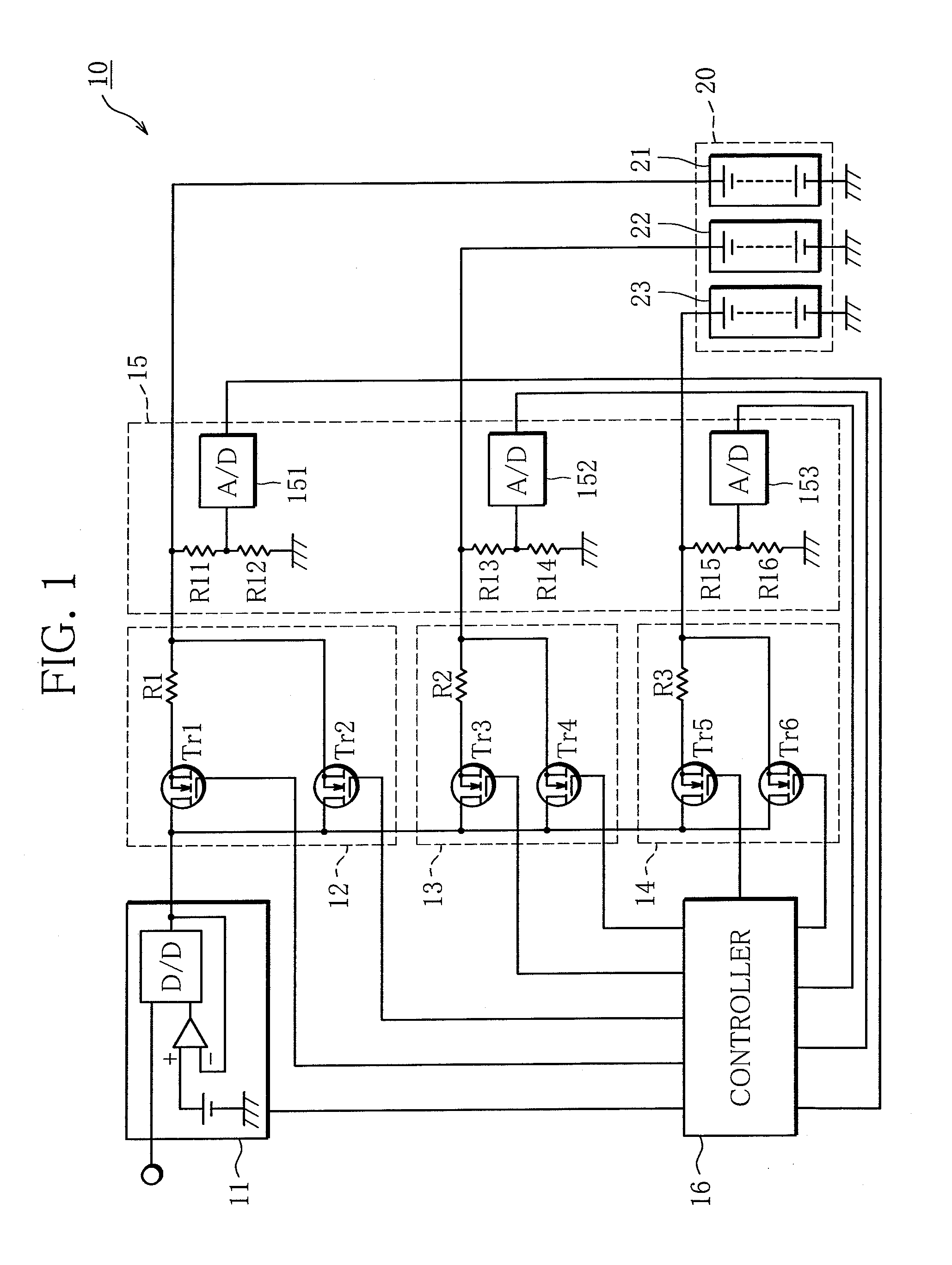
[0019]The configuration of a charger 10 of the present invention will be described below with reference to FIG. 1.

[0020]FIG. 1 is a view showing a whole configuration of the charger 10.

[0021]The charger 10 has a power source device 11, a first charging circuit 12, a second charging circuit 13, a third charging circuit 14, a battery voltage detection circuit 15 and a controller 16. A multi-parallel battery pack 20 charged by the charger 10 includes three battery banks 21 to 23. The battery banks 21 to 23 are rechargeable batteries such as nickel-hydrogen secondary batteries. The number of battery banks of the multi-parallel battery pack 20 to be charged according to the invention is not particularly limited to three as long as the battery pack 20 includes two or more battery banks.

[0022]The power source device 11 serving as a “constant voltage and constant cur...


PUM


Abstract

The charger 10 includes a first charging path that charges battery banks via current limiting resistors R1 to R3, a second charging path that charges the battery banks without passing through the current limiting resistors R1 to R3, and a circuit that is capable of selectively switching the first and second charging paths to one another, being provided to the respective battery banks, and being identical in resistance values of the current limiting resistors R1 to R3. A battery voltage detection circuit detects the voltages of the battery banks; and a controller 16 controls the first to third charging circuits so that the battery banks are charged through the first charging path when there is difference in the voltages of the battery banks. The battery banks are charged through the second charging path when there is no difference in the voltages of the battery banks.

Description

BACKGROUND OF THE INVENTION [0001]1. Field of the Invention[0002]The present invention relates to a charger that charges a plurality of batteries all at a time, or more specifically, a charger that charges, for example, a multi-parallel battery pack.[0003]2. Description of the Related Art[0004]A common charger that charges a multi-parallel battery pack consisting of a plurality of battery banks is one that finishes the charging at the time point when any one of the battery banks is fully charged, regardless of whether or not the other battery banks are fully charged. At the start of charging, battery banks usually have different state of charge. After any one of the battery banks is fully charged, if the charging is continued until all the other battery banks are fully charged, the first fully charged battery bank will be overcharged and might be deteriorated. For this reason, there is high possibility that a multi-parallel battery pack that is charged by a conventional charger mixe...

Claims


Application Information

Patent Timeline
Patent Type & Authority Applications(United States)
IPC IPC(8): H02J7/00H02J7/02
CPCH02J7/0018
Inventor KABASAWA, TAKASHIHONMA, HISANORI
Owner FDK CORP
Why Eureka
Try Eureka