Image processing device, imaging device, and image processing method

a technology of image processing and imaging device, which is applied in the field of image processing device, imaging device, and image processing method, can solve the problems of affecting the captured image, unnecessary light that looks like a double image, and unnecessary light in the captured image, so as to reduce unnecessary light

Active Publication Date: 2012-11-15
PANASONIC CORP
View PDF6 Cites 6 Cited by
  • Summary
  • Abstract
  • Description
  • Claims
  • Application Information

AI Technical Summary

Benefits of technology

[0014]According to the present invention, it is possible to generate, based on one captured image capturi...

Problems solved by technology

When an image of a bright object is captured by an imaging device that captures an object, unnecessary light in a captured image can be large enough to be visible, adversely affecting the captured image.
Especially when a diffractive lens having a d...

Method used


Image

  • Image processing device, imaging device, and image processing method
  • Image processing device, imaging device, and image processing method
  • Image processing device, imaging device, and image processing method

Examples


embodiment

[0078]The following describes an embodiment of the present invention with reference to the drawings.

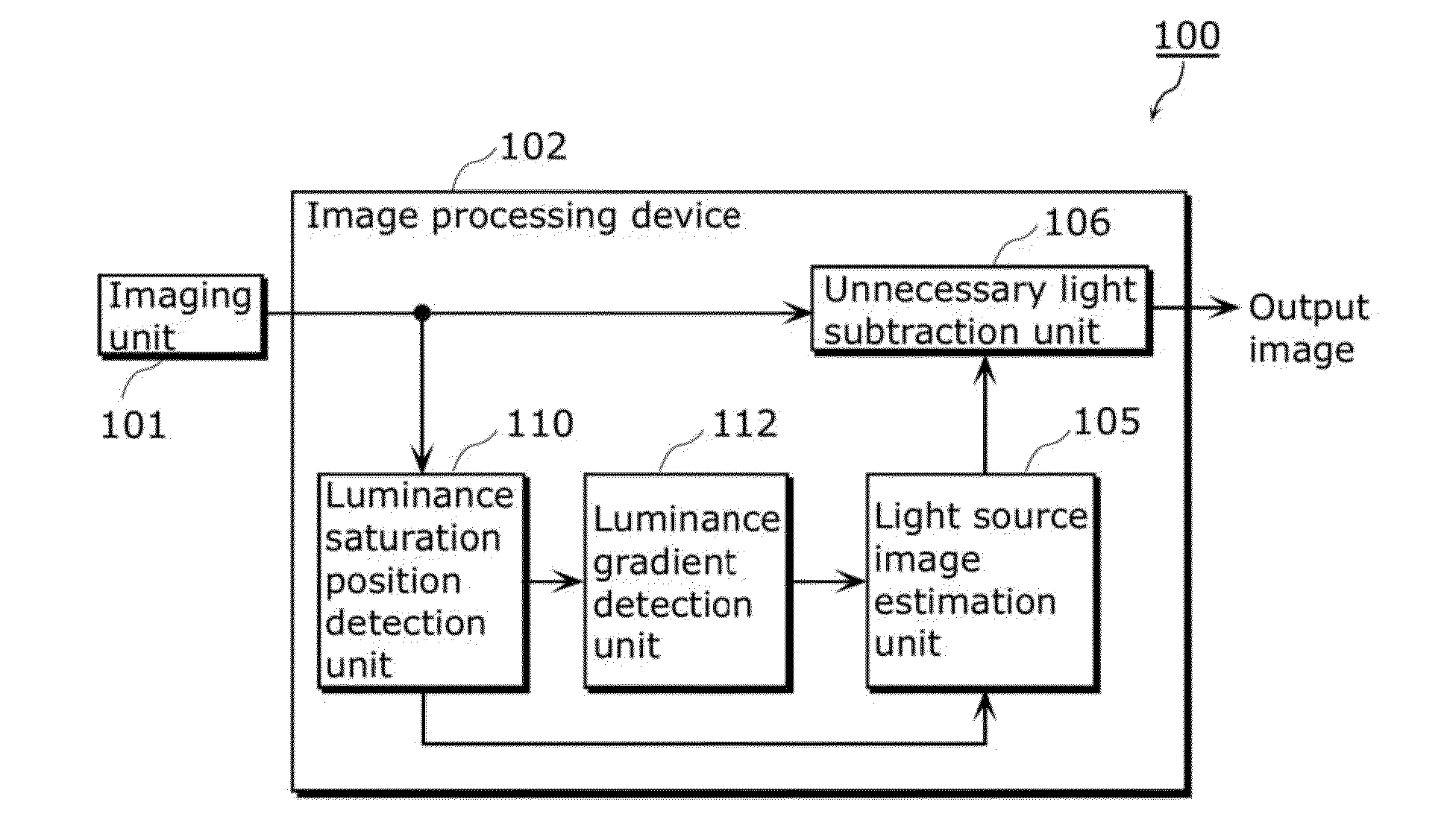
[0079]FIG. 7A is a block diagram showing a structure of an imaging device 100 according to the embodiment of the present invention. FIG. 7B is a block diagram showing an example of a structure of a light source image estimation unit according to the embodiment of the present invention. In FIG. 7A, the imaging device 100 includes: an imaging unit 101 and an image processing device 102.

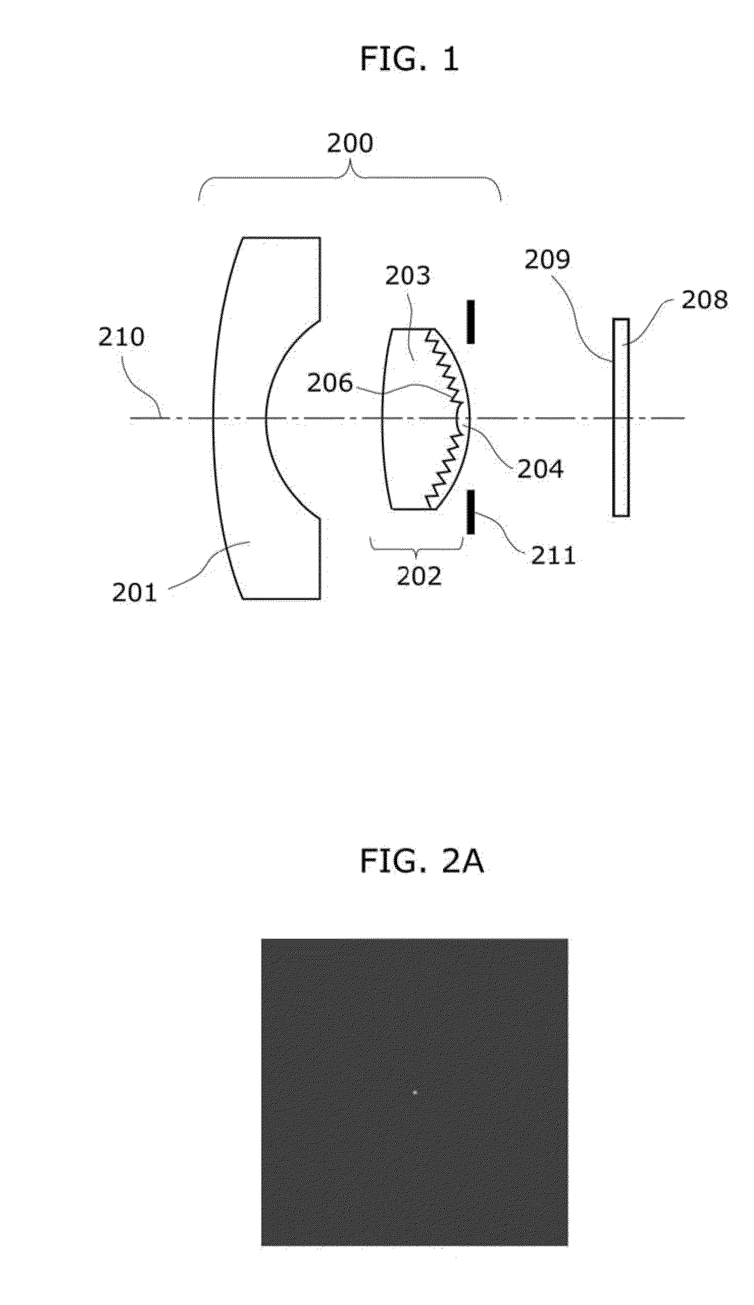
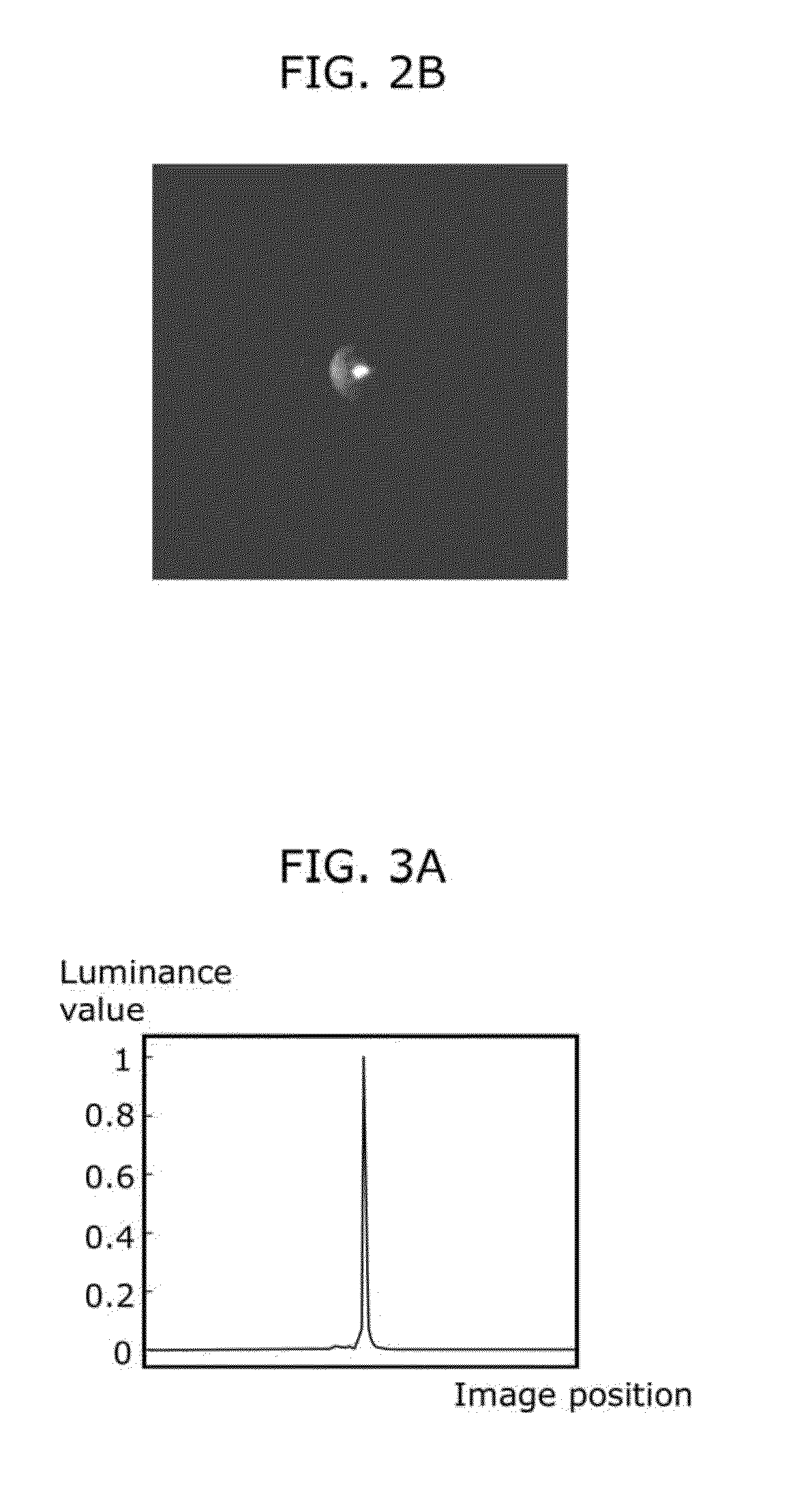
[0080]The imaging unit 101 includes the optical system 200 and the imaging element 208 shown in FIG. 1. The imaging unit 101 captures an image of an object, and outputs a captured image It(x, y). Here, “x” and “y” represent an image position in the horizontal direction and the vertical direction of the image, respectively. Note that the image position is a position on the captured image. For example, the image position indicates the position of each of the pixels included in the captured image.

[0081]The i...


PUM


Abstract

An image processing device includes: a luminance saturation position detection unit which detects a luminance saturation position that is a position in a captured image at which a luminance value is greater than a predetermined value; a luminance gradient detection unit which detects a luminance gradient around the luminance saturation position; a light source image estimation unit which estimates a luminance distribution on an imaging surface, based on (i) an image at the luminance saturation position, (ii) a point spread function image which corresponds to the luminance saturation position, and (iii) the luminance gradient, such that the luminance value increases as the luminance gradient increases, the luminance distribution being formed by an object whose image is captured at the luminance saturation position; and an unnecessary light subtraction unit which subtracts a luminance value of unnecessary light from the captured image by using the luminance distribution.

Description

TECHNICAL FIELD[0001]The present invention relates to techniques for reducing unnecessary light (flare) in captured images by image processing after images are captured, when bright objects are captured and large unnecessary light is included in the captured images.BACKGROUND ART[0002]When an image of a bright object is captured by an imaging device that captures an object, unnecessary light in a captured image can be large enough to be visible, adversely affecting the captured image. Especially when a diffractive lens having a diffraction grating is used, the unnecessary light can be larger than when an aspheric lens is used. For example, unnecessary light that looks like a double image can appear in the captured image, when a light source such as a fluorescent lamp is captured.[0003]Examples of conventional techniques that reduce such unnecessary light by image processing include techniques described in Patent Literatures (PTLs) 1 and 2. According to PTL 1, the unnecessary light i...

Claims


Application Information

Patent Timeline
IPC IPC(8): H04N9/68
CPCH04N5/217H04N5/23229G06T2207/10024G06T5/005G06T5/008H04N1/4072H04N23/81H04N23/80
Inventor OYAMA, ICHIRO
Owner PANASONIC CORP
Why Eureka
Try Eureka