
Optical Filter and Its Applications, and Porphyrin Compound Used in Optical Filter

a technology which is applied in the field of optical filters and porphyrin compounds used in optical filters, can solve the problems of reducing the color reproductivity (color purity) of an image, reducing the brightness of a display unit, and reducing the external light. , to achieve the effect of reducing unnecessary light, excellent durability and improving contrast in a bright pla

Inactive Publication Date: 2007-12-20
MITSUI CHEM INC
View PDF0 Cites 20 Cited by
  • Summary
  • Abstract
  • Description
  • Claims
  • Application Information

AI Technical Summary

Benefits of technology

[0020] It is an object of the present invention to provide an optical filter which is capable of eliminating an unnecessary emission of a display unit and an unnecessary light mainly existing in a wavelength range of from 530 to 570 nm contained in external light without preventing a necessary emission of the display unit, and which is excellent in durability as well. In particular, it is an object of the present invention to provide an optical filter capable of realizing a display unit which is excellent in contrast in a bright place and color purity of luminescent color.
[0040] The optical filter of the present invention is capable of reducing an unnecessary light mainly existing in a wavelength of from 520 to 700 nm and is also excellent in durability. For this reason, the optical filter is considered to be particularly suitable as an optical filter for consumer use in which durability is valued. Further, in a display unit using the optical filter of the present invention, contrast in a bright place can be improved and at the same time color purity of luminescent color can be improved. Accordingly, industrial value of the present invention is great.

Problems solved by technology

However, in a bright place such as a fluorescent lamp or the like, the contrast of a display unit is generally decreased due to external light.
However, in this method, since a necessary emission emitted from the display unit is also cut off at the same time, luminance might also be decreased.
Color reproductivity (color purity) of an image is lost by this unnecessary emission.
In response to this, various methods have been studied in order to improve the color purity, but its effects are not sufficient (refer to Patent Documents 2 to 6).
However, even though a filter for effectively eliminating an unnecessary light mainly existing in the vicinity of 550 nm contained in a fluorescent lamp or the like due to a dye has been highly in demand from the market, the reality is that such a filter has not been put into practical use.
This is attributable to the fact that performance of the dye capable of absorbing an unnecessary light as described above is remarkably deteriorated under the conditions including environment of use and / or temperature, light, heat and the like caused by the display unit.
In particular, there has been a problem in durability when a dye is used in an adhesive.

Method used


Image

  • Optical Filter and Its Applications, and Porphyrin Compound Used in Optical Filter
  • Optical Filter and Its Applications, and Porphyrin Compound Used in Optical Filter
  • Optical Filter and Its Applications, and Porphyrin Compound Used in Optical Filter

Examples


example 1

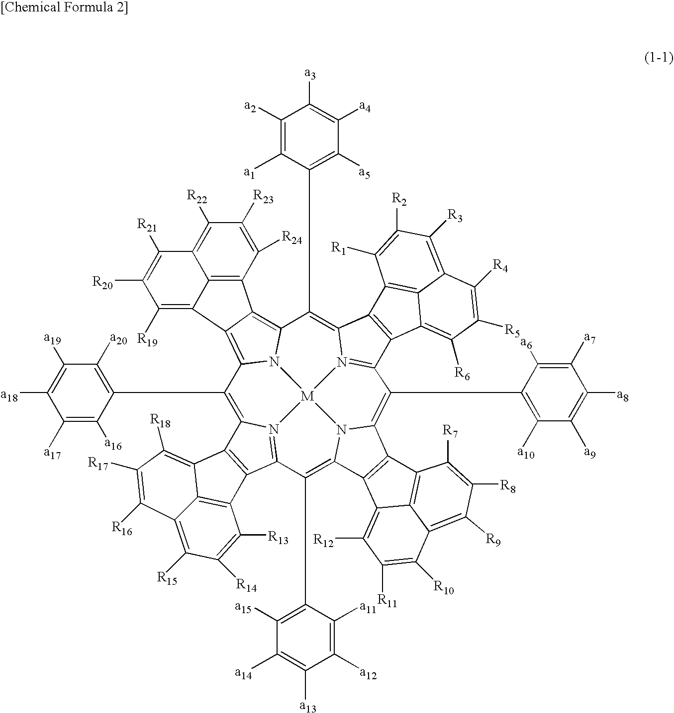
Compound Represented by the Above Formula (1-1) and Optical Filter Using the Compound

example 1-1

[0166] In a nitrogen atmosphere, into a flask were introduced 5.2 g of p-decyloxybenzaldehyde and 1 L of chloroform. Then, 4.0 g of acenaphthopyrrole was added thereto and the resulting mixture was stirred. 0.55 g of BF3.Et2O was added thereto and the mixture was stirred for 4 hours, and then 3.3 g of 2,3-dichloro-5,6-dicyano-1,4-benzoquinone was added and the mixture was stirred for 2 hours. The solvent was distilled off and then the residue was purified with a silica gel column. In the purification, chloroform (1% triethylamine contained) was used as a developing solution, whereby 7.8 g of a compound represented by the following formula (1-A) was obtained.

[0167] The maximum absorption wavelength in chloroform of the compound was 567 nm, while the gram absorption coefficient was 113,000.

[0168] Analysis data: 1H-NMR

[0169]δ (ppm): 8.65 (d, 8H), 7.62 (d, 8H), 7.42 (d, 8H), 7.20 (t, 8H), 5.88 (d, 8H), 4.33 (m, 8H), 2.03 (m, 8H), 1.63 (m, 8H), 1.5-1.2 (m, 48H), 0.93 (t, 12H).

example 1-2

[0170] In a nitrogen atmosphere, into a flask were introduced 1.5 g of the obtained compound represented by the above formula (1-A), 0.32 g of nickel (II) acetate and 300 ml of DMF. The resulting mixture was stirred at 120° C. for 2 hours, cooled down, and then extracted with chloroform and washed with water. The solvent was distilled off and then the residue was purified with a silica gel column. In the purification, a mixed solvent of toluene and hexane (mixing ratio: 7:3, volume) was used as a developing solution, whereby 0.4 g of a compound represented by the compound No. 1-6 (Table 1-1) was obtained.

[0171] The maximum absorption wavelength in chloroform of the compound was 536 nm, while the gram absorption coefficient was 135,000.

[0172] Analysis data: 1H-NMR

[0173]δ(ppm): 8.36 (d, 8H), 7.61 (d, 8H), 7.33 (d, 8H), 7.18 (t, 8H), 5.80 (d, 8H), 4.29 (m, 8H), 2.01 (m, 8H), 1.64 (m, 8H), 1.5-1.2 (m, 48H), 0.92 (t, 12H).


PUM

PropertyMeasurementUnit
wavelength rangeaaaaaaaaaa

Abstract

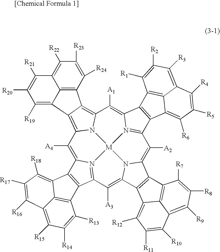
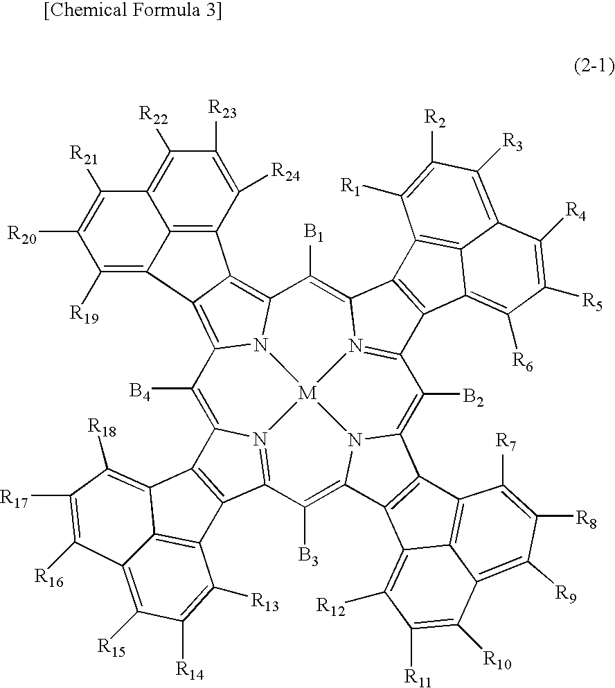
An optical filter of the present invention contains at least one tetra-acenaphthoporphyrin compound. The tetra-acenaphthoporphyrin compound has preferably its absorption maximum in a wavelength range of from 530 to 570 nm and a ratio of an absorption coefficient at 550 nm to an absorption coefficient at 525 nm of not less than 1.2. Also, a percentage of light transmittance at 550 nm to light transmittance at 525 nm is preferably not more than 85%. According to the present invention, it is possible to provide the optical filter which can eliminate an unnecessary light mainly existing in a wavelength of from 520 to 700 nm and is excellent in durability. A display unit using the optical filter of the present invention can improve contrast in a bright place, and improve color purity of luminescent color.

Description

TECHNICAL FIELD [0001] The present invention relates to an optical filter and a porphyrin compound used in the optical filter. More particularly, the present invention relates to an optical filter capable of realizing a display unit which is excellent in durability, and is particularly excellent in contrast in a bright place and color purity of luminescent color, and a porphyrin compound used in the optical filter. BACKGROUND ART [0002] In late years, with the sophisticated society, optoelectronics-related components and equipments have been remarkably advanced day by day. Among others, a display presenting pictures has been remarkably spread and developed for use in computer monitor devices and the like, in addition to conventional television receivers. With the development of these devices, particularly, a large-scale, thinned, and high quality display has been in high demand from the market. [0003] In recent years, when they are used as a display, full color display is natural. I...

Claims


Application Information

Patent Timeline
Patent Type & Authority Applications(United States)
IPC IPC(8): C07D487/22
CPCG02B5/223C07D487/22G02B5/20C08J5/18
Inventor MINAMI, HIROMIOKAMURA, TOMOYUKIKAGAYAMA, AKIFUMISUZUKI, RIHOKOFUJII, KENICHIOI, RYUNISHIMOTO, TAIZOMOROHASHI, MAKOTOMISAWA, TSUTAMIFUKUDA, SHIN
Owner MITSUI CHEM INC
Learn More