
LCD Device and Back Cover Thereof

a back cover and liquid crystal display technology, applied in the field of liquid crystal display, can solve the problems of high production cost, complex structure of lcd device, high production cost, etc., and achieve the effect of reducing the structural complexity, reducing the production cost of lcd device, and simplifying the assembling process of lcd devi

Active Publication Date: 2012-11-15
SHENZHEN CHINA STAR OPTOELECTRONICS TECH CO LTD
View PDF2 Cites 38 Cited by
  • Summary
  • Abstract
  • Description
  • Claims
  • Application Information

AI Technical Summary

Benefits of technology

[0005]The primary objective of the present invention is to provide a liquid crystal display (LCD) device and a back cover thereof which can reduce the structural complexity and the production cost of the LCD device.
[0025]The present invention has the following benefits: as compared to the prior art, the LCD device of the present invention uses the back cover to replace the metal backplate and the plastic mid-frame of the prior art LCD device. Because this reduces the structural complexity and the production cost of the LCD device, the assembling process of the LCD device is simplified and the competitive edge of the manufacturers is improved.

Problems solved by technology

Therefore, the prior art LCD device requires use of the plastic mid-frame, the metal backplate and the front frame in combination to fix other components, which makes the LCD device complex in structure and have a high production cost.
What is needed, therefore, is an LCD device and a back cover thereof that can solve the problems that the prior art LCD devices are complex in structure and have a high production cost.

Method used


Image

  • LCD Device and Back Cover Thereof
  • LCD Device and Back Cover Thereof

Examples


Embodiment Construction

[0028]Reference will now be made to the drawings to describe preferred and exemplary embodiments of the present invention in detail.

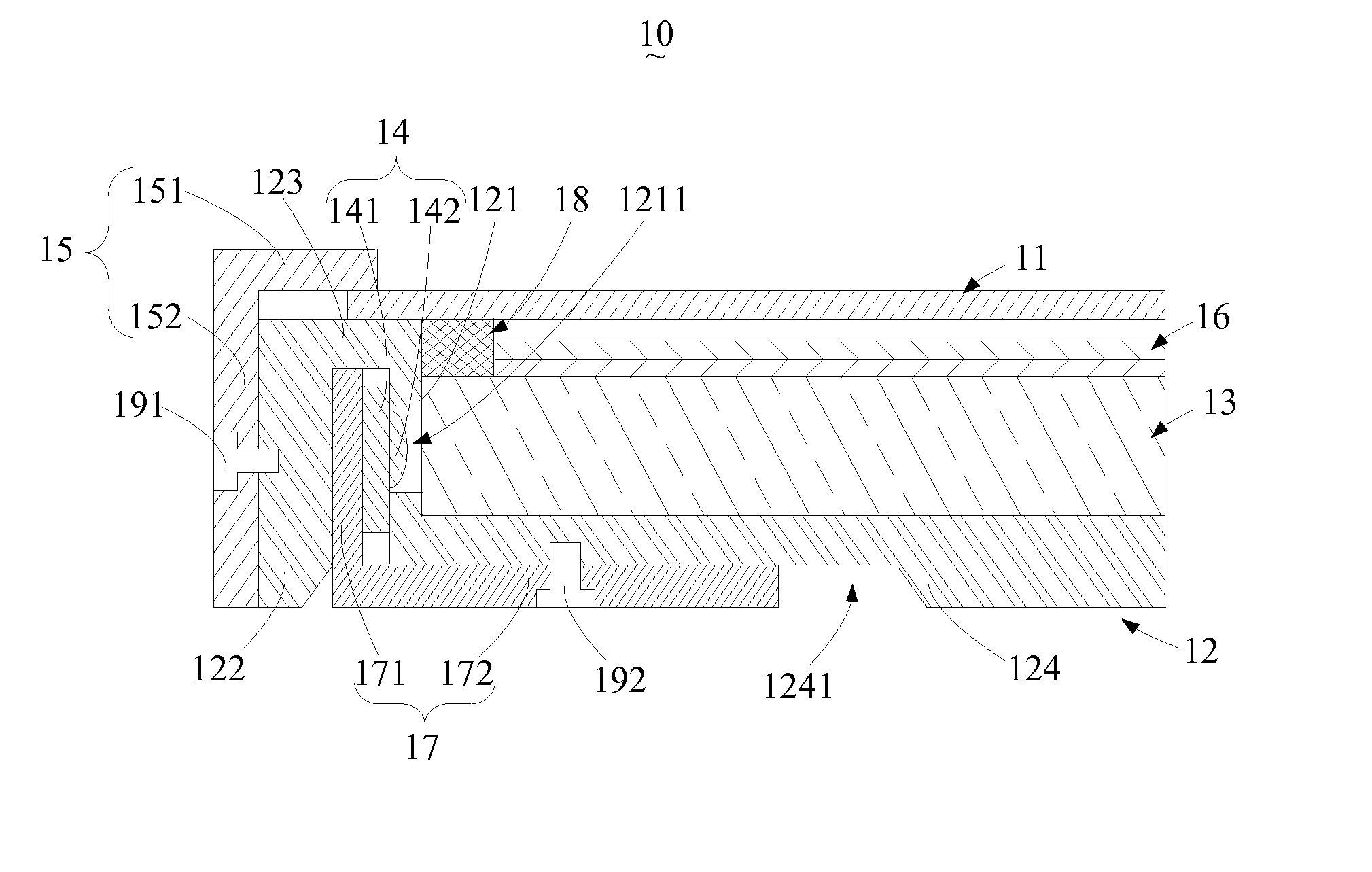
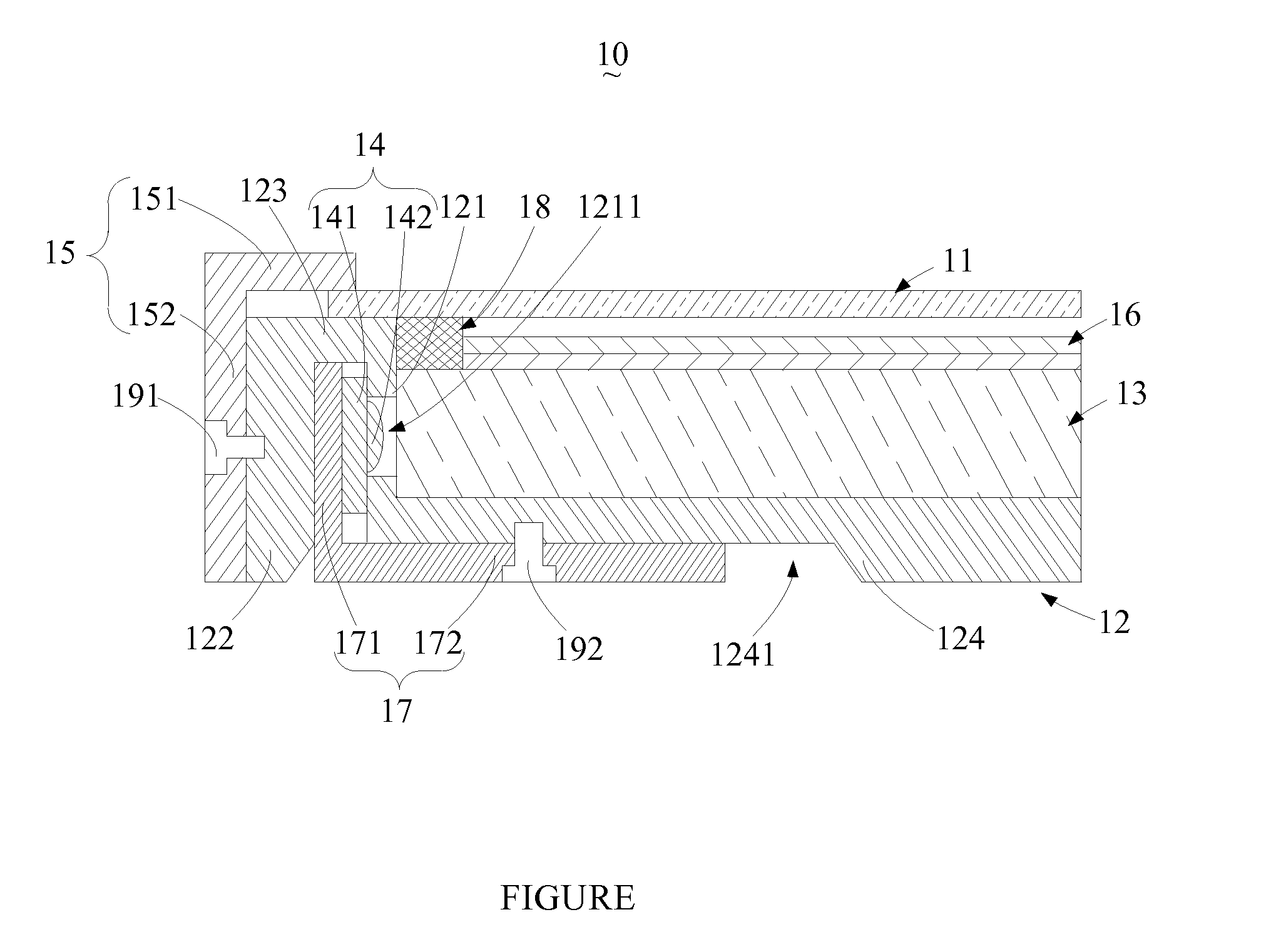
[0029]Referring to the FIGURE, there is shown a schematic cross-sectional view of a preferred embodiment of an LCD device according to the present invention. An LCD device 10 of the present invention comprises a liquid crystal panel 11, a back cover 12, a light guide plate 13, a light source 14, a front frame 15, an optical membrane 16, a heat dissipating plate 17 and a buffering element 18.

[0030]In this embodiment, the liquid crystal panel 11 extends in a first direction. In the FIGURE, the first direction is of a horizontal direction. However, it will be appreciated by those skilled in the art that, when the LCD device 10 is put in other orientations, the first direction may also be other directions.

[0031]In this embodiment, the back cover 12 comprises a first sidewall 121, a second sidewall 122, a first supporting wall 123 and a second supporting wal...


PUM


Abstract

The present invention provides a liquid crystal display (LCD) device and a back cover thereof. The LCD device comprises a liquid crystal panel, a back cover, a light guide plate and a light source. The back cover comprises a first sidewall, a second sidewall, a first supporting wall and a second supporting wall. The first sidewall and the second sidewall are spaced apart from each other to form a receiving space. The first supporting wall connects an end of the first sidewall and an end of the second sidewall. The second supporting wall extends away from the second sidewall and connects to the other end of the first sidewall. The liquid crystal panel is supported on a side of the first supporting wall that faces away from the first sidewall and the second sidewall. The light guide plate is supported on a side of the second supporting wall that faces towards the liquid crystal panel. The light source is disposed inside the receiving space. The first sidewall is formed with a through-hole for allowing light rays generated by the light source to pass therethrough into the light guide plate. With the aforesaid arrangement, the metal backplate and the plastic mid-frame used in the prior art LCD device can be replaced by the back cover to simplify the structure and lower the production cost of the LCD device.

Description

TECHNICAL FIELD[0001]The present invention generally relates to the field of liquid crystal displays (LCDs), and more particularly, to an LCD device and a back cover thereof.BACKGROUND[0002]Nowadays, owing to such advantages as lightweight, low-profile, low power consumption and free of radiation, liquid crystal displays (LCDs) have found wide application in various electronic products such as computers, TV sets, notebook computers, mobile phones and digital cameras. A typical LCD device in the prior art comprises a liquid crystal panel, a light source, a light guide plate, an optical membrane, a reflective sheet, a plastic mid-frame, a metal backplate and a front frame. The light guide plate, the optical membrane, the reflective sheet and the light source are disposed in a receiving space formed by the plastic mid-frame and the metal backplate, and are fixed therein by the plastic mid-frame. The liquid crystal panel is disposed on an upper surface of the plastic mid-frame and fixed...

Claims


Application Information

Patent Timeline
IPC IPC(8): G02F1/1333B65D6/00B65D85/00
CPCG02B6/0086G02F2001/133314G02F1/133308G02B6/0091G02F1/133314
Inventor QUE, CHENGWENHSIAO, YU-CHUN
Owner SHENZHEN CHINA STAR OPTOELECTRONICS TECH CO LTD
Learn More