Off-axis collimation optics

a collimation optics and off-axis technology, applied in the field of off-axis collimation optics, can solve the problems of inability to use configuration, inability to provide such beams from the center lens, and inability to be optimal, and achieve the effect of extending the tilt angle of the off-axis beam

Active Publication Date: 2012-11-15
SEOUL SEMICONDUCTOR
View PDF6 Cites 54 Cited by
  • Summary
  • Abstract
  • Description
  • Claims
  • Application Information

AI Technical Summary

Benefits of technology

[0008]The optical approach explained in detail below does not rely solely on the center lens of a photon funnel to provide off-axis illumination. Using the TIR reflective back surface of a photon funnel for off-axis illumination has several advantages, among them: that much more flux impinges upon this surface; and that by the nature of reflection, modifications of the back surface make much larger off-axis beam tilt angle possible than with a single refraction at the center lens. In all of the embodiments described below, the optical designs are modified rotational designs. The rotational designs are obtained with common methods, either with point source approximation numerical or analytic methods or with extended source optimization using common iterative numerical methods. The starting point design can be a narrow-beam on-axis collimator, or part of the surfaces can be calculated to provide a wider on-axis beam. In a subsequent step some optical surfaces are modified to deviate from the rotational symmetry. All other surfaces may be le

Problems solved by technology

If more or less light is wanted in the off-axis beam, this configuration cannot be used.
Moreover the center lens provides a relatively wide beam by nature of the lens 103, so that if a narrow off-axis beam is wanted,

Method used


Image

  • Off-axis collimation optics
  • Off-axis collimation optics
  • Off-axis collimation optics

Examples


Embodiment Construction

[0025]A better understanding of the features and advantages of the present invention will be obtained by reference to the following detailed description of the invention and accompanying drawings, which set forth illustrative embodiments in which the principles of the invention are utilized.

[0026]In the following drawings all architectures are described in more detail:

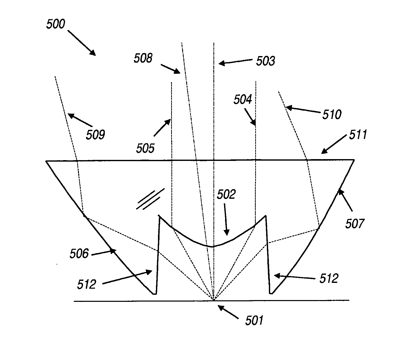
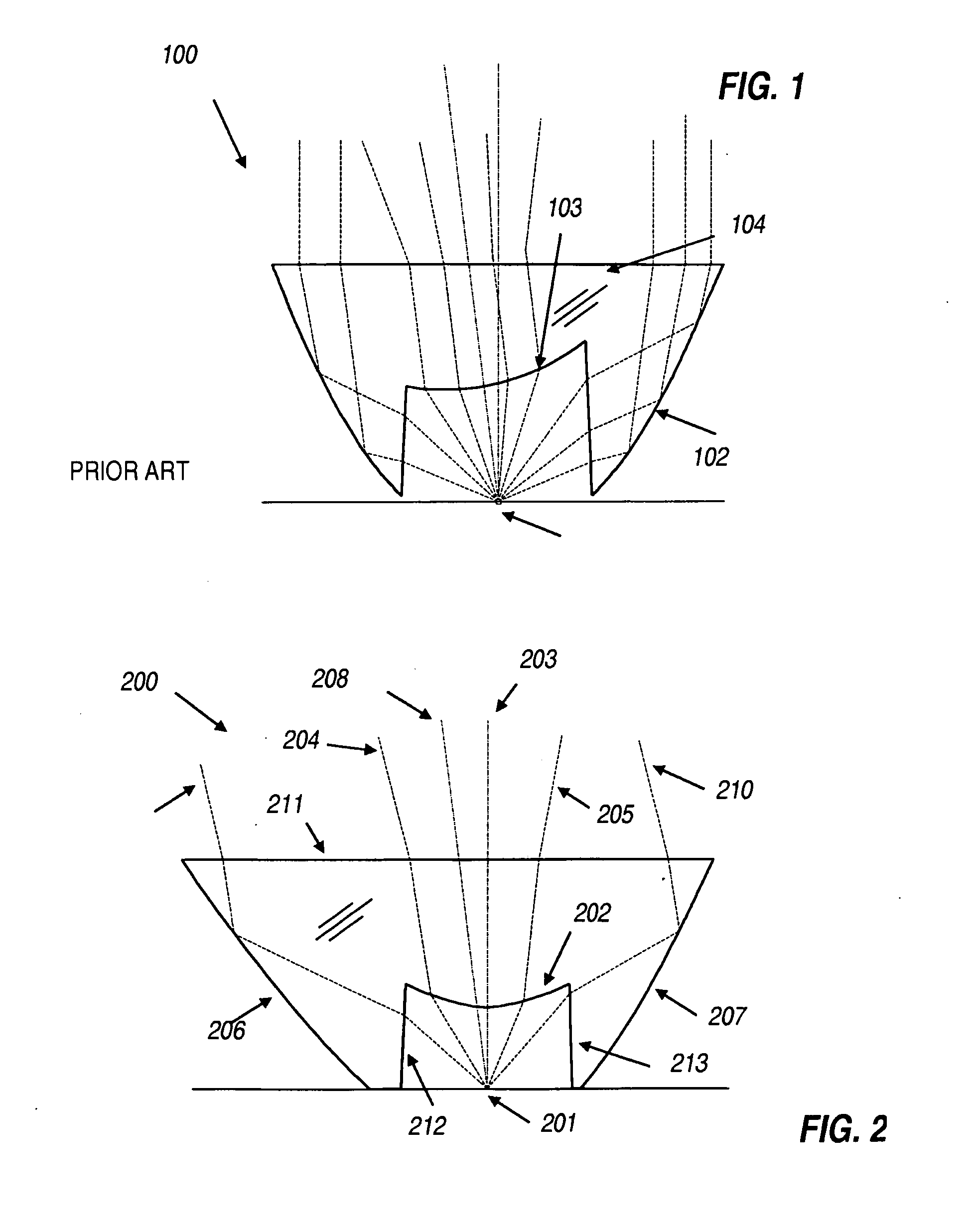
[0027]Referring to FIG. 2, a lens 200 represents a photon funnel that collimates the light from a source 201 into an off-axis hot spot and also creates a low-intensity background illumination. The photon funnel 200 comprises a dielectric lens with a central cavity. Lines 212 in FIG. 2 are cross sections of a conical surface of rotation with respect to the source axis 203, forming the side wall of the cavity. Surface 202 forms a central lens, closing off the front end of the cavity, and is a rotationally symmetric surface around axis 203. Lens surface 202 is shaped so that rays such as 204 and 205 that are refracted at ...


PUM


Abstract

A light funnel collimator has a central lens surface and a back reflecting surface, shaped to provide a wider back-ground beam and a narrower hotspot beam within but off-center of the wider beam. One of the beams is on-axis of the collimator, and the other beam is off-axis. The reflector is at least partly asymmetrical relative to the axis, and provides or contributes to the off-axis beam.

Description

CROSS REFERENCE TO RELATED APPLICATION[0001]This application claims benefit of U.S. Provisional Patent Application No. 61 / 298,030, filed Jan. 25, 2010 by Dross et al. for “Off-axis collimation optics.”BACKGROUND OF THE INVENTION[0002]Light emitting diodes (LEDs) are widely available, inexpensive, and efficient light sources. For uses such as sport headlamps, one or two state of the art LEDs provide adequate light. While simple light distributions of rotational symmetry are sufficient for low quality products or less demanding uses, more complex light distributions are being employed for better vision when walking, running, or cycling with a headlamp. It is beneficial to produce a relatively narrow hotspot of typically 10° full width at half maximum (FHWM) so to illuminate objects far away from the user, while a lower level intensity background light is needed to provide lighting of the ground close to the user. Such a background light is not needed upwards from the hotspot so that a...

Claims


Application Information

Patent Timeline
IPC IPC(8): G02B27/30
CPCF21V5/04F21V7/0091F21Y2101/02G02B19/0061H01L33/58F21W2131/103G02B19/0028G02B17/086F21V5/08F21Y2115/10C07K14/005C07K2319/21C07K2319/23C12N15/70C12N2750/10022C12N2800/22
Inventor DROSS, OLIVERMUNOZ, FERNANDO
Owner SEOUL SEMICONDUCTOR
Why Eureka
Try Eureka