
Universal mounting bracket with optical functions for use with auxiliary optical devices

Inactive Publication Date: 2012-11-15
GABER LEONID
View PDF8 Cites 5 Cited by
  • Summary
  • Abstract
  • Description
  • Claims
  • Application Information

AI Technical Summary

Benefits of technology

[0013]The power of the light emitted by the LED should be

Problems solved by technology

However, such optical sights are very expensive devices.
In addition to high cost, the known optical sights are not sufficiently universal and are intended only for their specific use.
Furthermore, although the use of two mounts is undesirable because they add weight and are more expensive, during the use of a day-vision monocular the quality of the target viewed by the viewer is satisfactory, whereas during the use of a night-vision monocular the quality of the target viewed by the viewer is very poor.
Furthermore, for better reflection of the red-dot image, the glass of the red-dot device is coated with an antireflective coating, and this impairs the quality of the target view.

Method used


Image

  • Universal mounting bracket with optical functions for use with auxiliary optical devices
  • Universal mounting bracket with optical functions for use with auxiliary optical devices
  • Universal mounting bracket with optical functions for use with auxiliary optical devices

Examples


Embodiment Construction

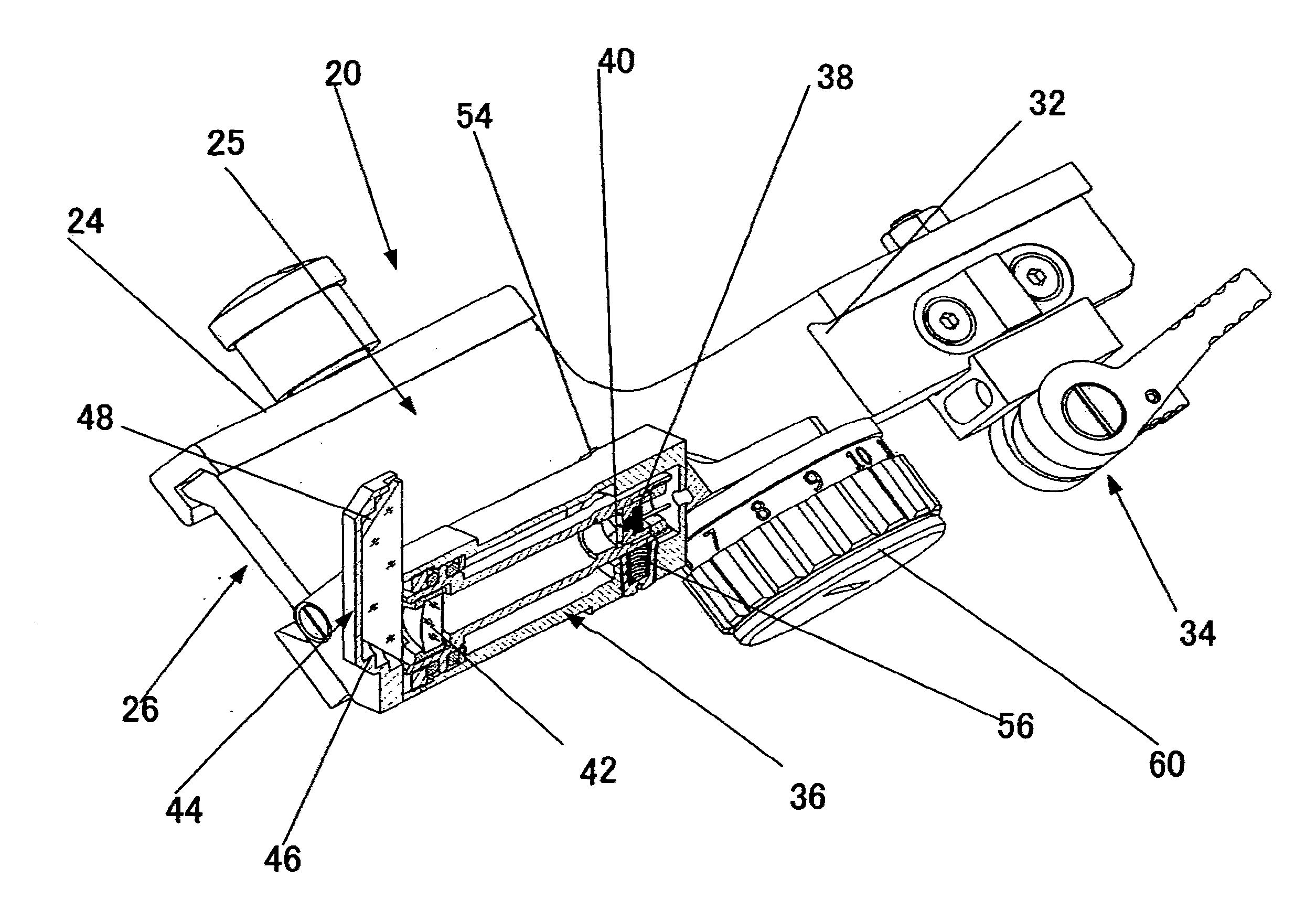
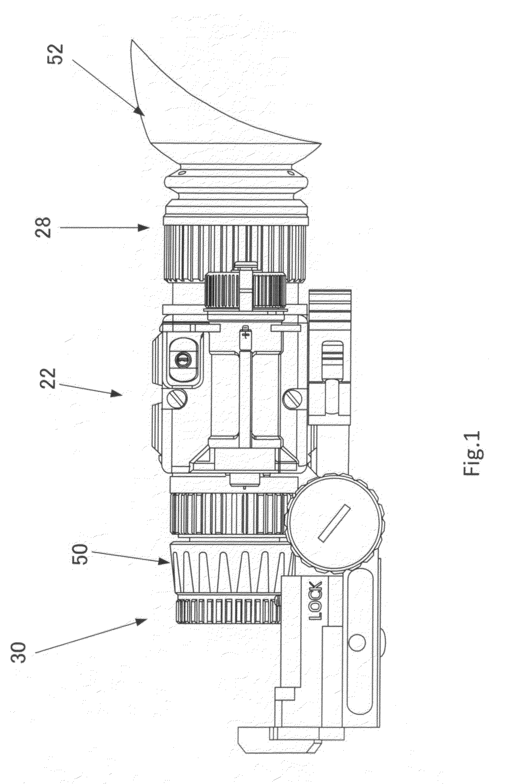
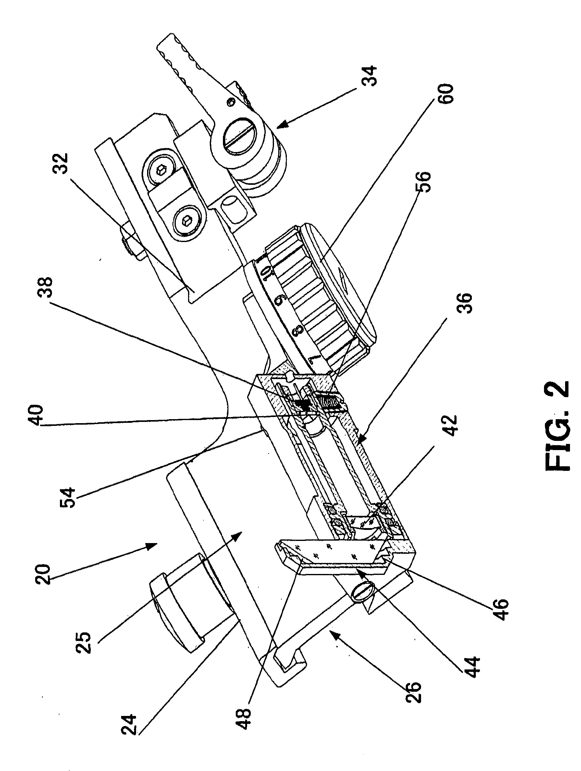
[0017]The mounting bracket of the invention is shown in the attached drawings, where FIG. 1 is a side view of an optical scope installed on the mounting bracket of the invention. FIG. 2 is a three-dimensional view of the mounting bracket of the invention with a cutaway portion showing the structure of the optical components of the bracket. FIG. 3 is another three-dimensional view of the mounting bracket with a cutaway portion showing the structure of the battery compartment.

[0018]The present invention provides a mounting bracket 20 for attachment to a weapon, e.g., a rifle (not shown in the drawings), of various auxiliary optical devices such as daylight-vision optical scopes, night-vision monoculars, etc. In FIG. 1, such an optical device is shown as a night-vision monocular 22.

[0019]A distinctive feature of the mounting bracket 20 of the invention is that the bracket 20 incorporates an optical system for projection of an image of the reticle without use of an additional mount and ...


PUM


Abstract

The invention provides a mounting bracket for attachment of various auxiliary optical devices such as daylight-vision optical scopes, night-vision monoculars, etc., to a weapon. A distinctive feature of the mounting bracket is that the bracket, itself, incorporates an optical system for projection of an image of the reticle (or other patterns) without use of additional mounts or external reticle or red-dot devices. Most importantly, the bracket allows use of inexpensive optical devices, e.g., a standard monocular, which can be used as a universal optical device, such as an optical sight, a spotting scope, a goggle, a part of a red-dot aiming system, or the like.

Description

FIELD OF THE INVENTION[0001]This invention relates to an arms sight and, more particularly, to brackets for mounting various auxiliary optical attachments and devices to a basic optical scope. More specifically, the invention relates to a mounting bracket for attaching such devices as day-vision optical scopes and night-vision monoculars to a weapon for use as an optical scope.DESCRIPTION OF THE PRIOR ART[0002]A conventional weapon such as a rifle has a mechanical iron sight on the target sight and a rear sight on the viewer sight, and for aiming the weapon must be placed into the position at which the image of the iron sight is aligned with the center of the rear sight. In order to facilitate aiming and to improve accuracy in aligning the front and rear sights, various optical devices that have the image of a reticle or a red dot are used. This is achieved with the use of optical sights.[0003]A great variety of optical sights and scopes differ not only by their functions, such as d...

Claims


Application Information

Patent Timeline
IPC IPC(8): F21V14/00F21V7/00
CPCF41G11/003F21Y2101/02F41G1/345F41G1/30F21Y2115/10
Inventor GABER, LEONID
Owner GABER LEONID
Learn More