Selectable lethality, focused fragment munition and method of use

Inactive Publication Date: 2012-11-22
WILSON DENNIS E +2
View PDF4 Cites 12 Cited by
  • Summary
  • Abstract
  • Description
  • Claims
  • Application Information

AI Technical Summary

Benefits of technology

[0020]In yet another embodiment, the method of selectively detonating the

Problems solved by technology

These types of munitions are highly indiscriminant in that they will produce substantial damage within a large lethality radius.
In such situations, traditional munitions can produce undesirable collateral damage to personnel and property.
Such munitions could decrease collateral damage in war zones, but the Guirguis munition's blast footprint is limited to a

Method used


Image

  • Selectable lethality, focused fragment munition and method of use
  • Selectable lethality, focused fragment munition and method of use
  • Selectable lethality, focused fragment munition and method of use

Examples


Embodiment Construction

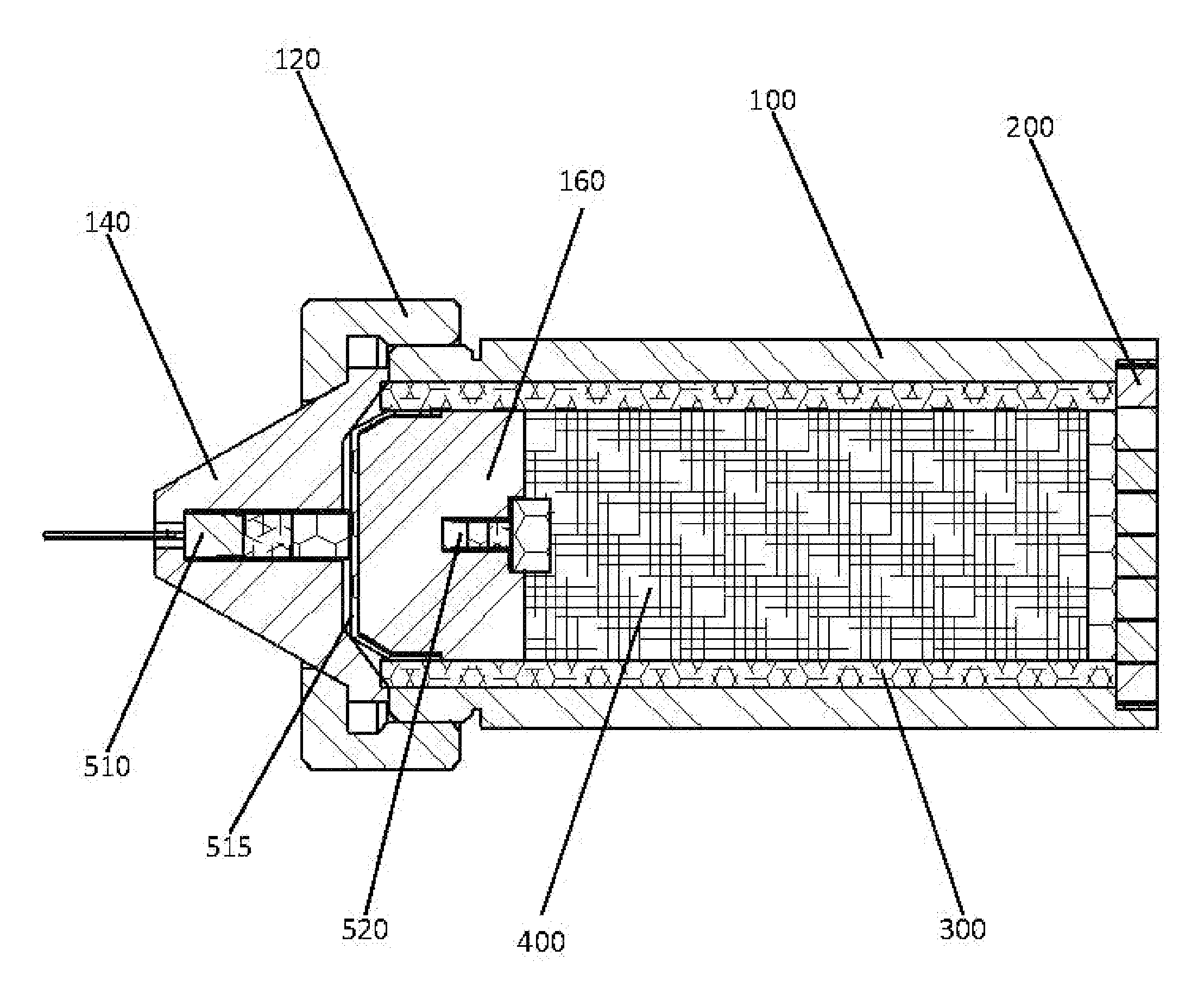
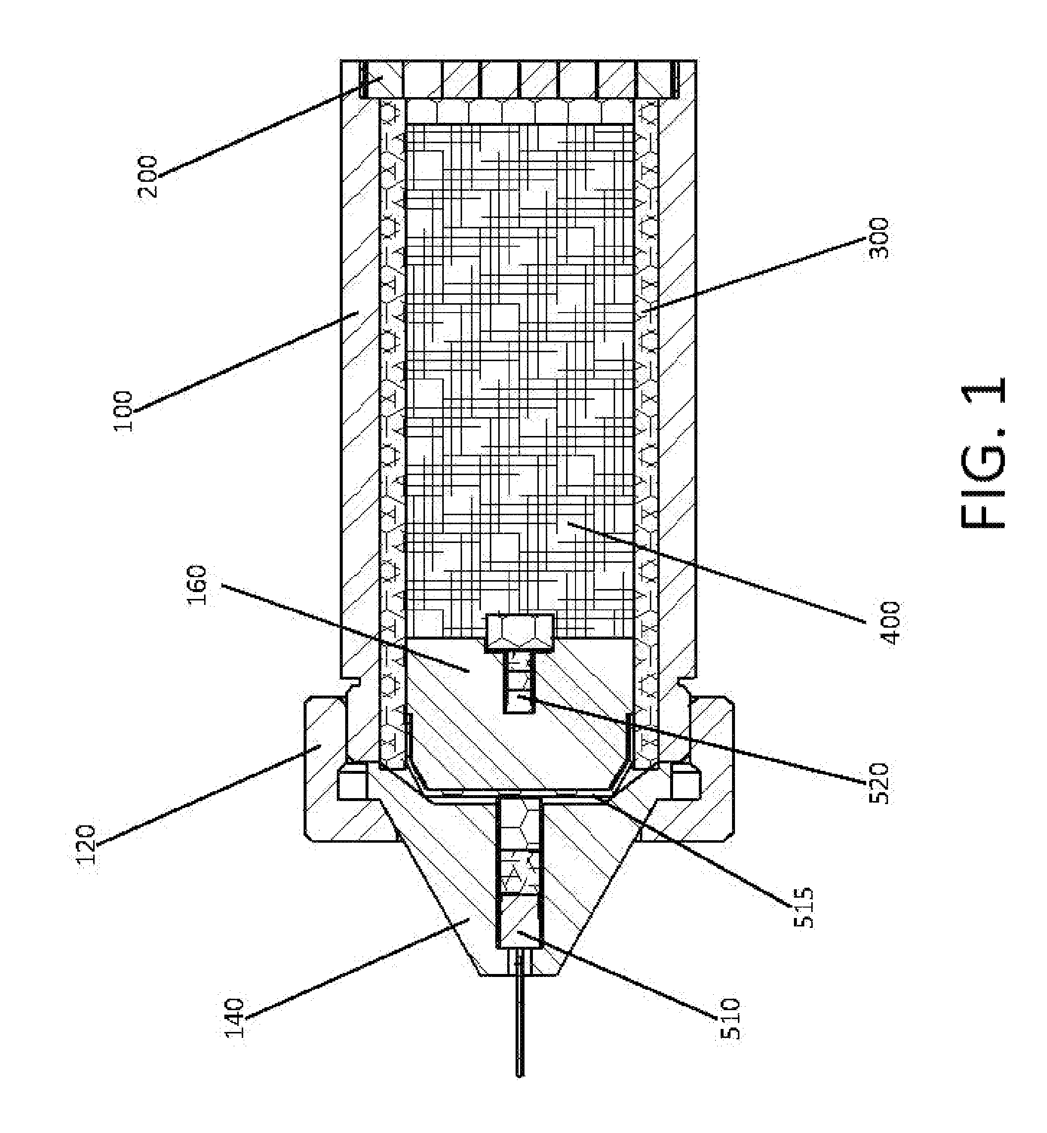
[0024]As shown in FIG. 1, the preferred embodiment of the current invention apparatus has a case 100 that has a preformed focused fragment end cap 200 on one end and a detonator housing 140 on the other end. The detonator housing 140 is secured to the case 100 with the threaded retaining ring 120, but could also be integral with the case. The detonator housing 140 contains the first detonator 510. The case 100 also contains a shock attenuating detonator housing 160 and a second detonator 520. The shock attenuating detonator housing 160 significantly reduces the transmitted shock pressure. It is comprised of a homogeneous, low density, highly compressible material, but can also be comprised of a heterogeneous, highly dissipative material such as soft granular particles. Shock attenuating detonator housing porosities can range from 10% to 50%. Examples include, but are not limited to, polymers such as polyethylene and polystyrene, and epoxy containing hollow micro-spheres.

[0025]The ca...


PUM


Abstract

A munition and method capable of producing real-time selectable effects ranging from unrestricted to low collateral damage. The munition is capable of a directionally focused fragment pattern and limited lethality/damage effects.

Description

[0001]This invention was made with Government support under FA8651-07-C-0153 awarded by the United States Air Force and Government support under W911QX-10-C-0019 awarded by the United States Army. The Government has certain rights in the invention.FIELD OF THE INVENTION[0002]The current invention relates to the field of munitions capable of directionally focused fragmentation.BACKGROUND OF THE INVENTION[0003]Munitions are typically designed for the specific purpose of creating the maximum lethality or destruction for a given munition volume or weight. Typical munitions utilize a metal case containing explosive material. Detonation of the explosive material fragments the case into high velocity shrapnel that damages or obliterates the target(s). These types of munitions are highly indiscriminant in that they will produce substantial damage within a large lethality radius. Such design has been beneficial in conventional force-on-force warfare where collateral damage is of minimal conc...

Claims


Application Information

Patent Timeline
IPC IPC(8): F42B12/22
CPCF42B12/32F42B12/24
Inventor WILSON, DENNIS E.GRANIER, JOHN J.JOHNSON, RICHARD V.
Owner WILSON DENNIS E
Why Eureka
Try Eureka