
Fabric belt for a machine for producing web material, in particular paper or cardboard

a technology of fabric belt and machine, which is applied in the direction of machine wet end, papermaking, textiles and paper, etc., to achieve the effect of reducing the tendency to mark

Inactive Publication Date: 2012-11-22
VOITH PATENT GMBH
View PDF5 Cites 2 Cited by
  • Summary
  • Abstract
  • Description
  • Claims
  • Application Information

AI Technical Summary

Benefits of technology

[0007]It is the objective of the current invention to design a fabric belt for a machine to produce a web material, in particular paper or cardboard, for example a forming fabric in such a way that an additional reduction in the tendency to mark can be achieved.
[0019]A further reduction in marking tendency can be achieved in that a number ratio of binding segments in the first fabric layer, relative to binding segments in the second fabric layer, is greater than 1. By providing a lower number of binding segments in the second fabric layer it becomes possible to leave a comparatively large space between the individual binding segment diagonals.
[0020]It is further suggested that a number ratio of basic weave threads of the first fabric layer extending transversely to the binding thread direction and basic weave threads of the second fabric layer is greater than 1. By providing such a ratio it becomes possible to superimpose an aspect of non-uniformity in the second fabric layer over the comparatively high uniformity in the first fabric layer, resulting in an accordingly reduced marking tendency.

Problems solved by technology

This uncontrolled cluster formation leads to an unexpected strong marking tendency which, based on the arbitrary distribution of the binding segments was not expected to occur to the same extent.

Method used


Image

  • Fabric belt for a machine for producing web material, in particular paper or cardboard
  • Fabric belt for a machine for producing web material, in particular paper or cardboard
  • Fabric belt for a machine for producing web material, in particular paper or cardboard

Examples


Embodiment Construction

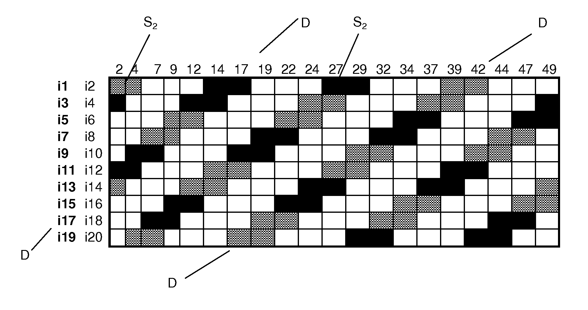
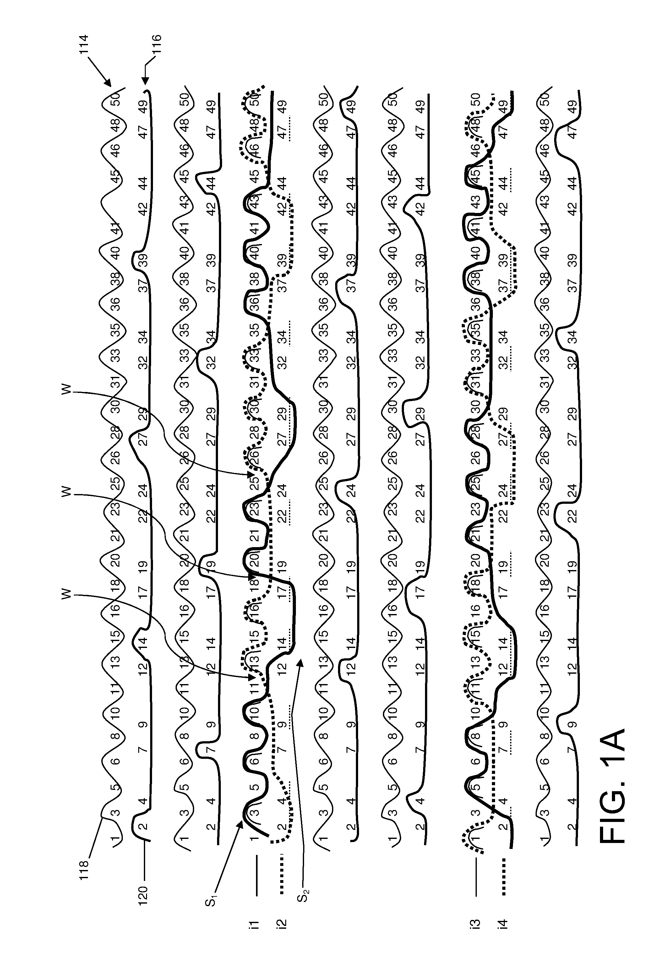
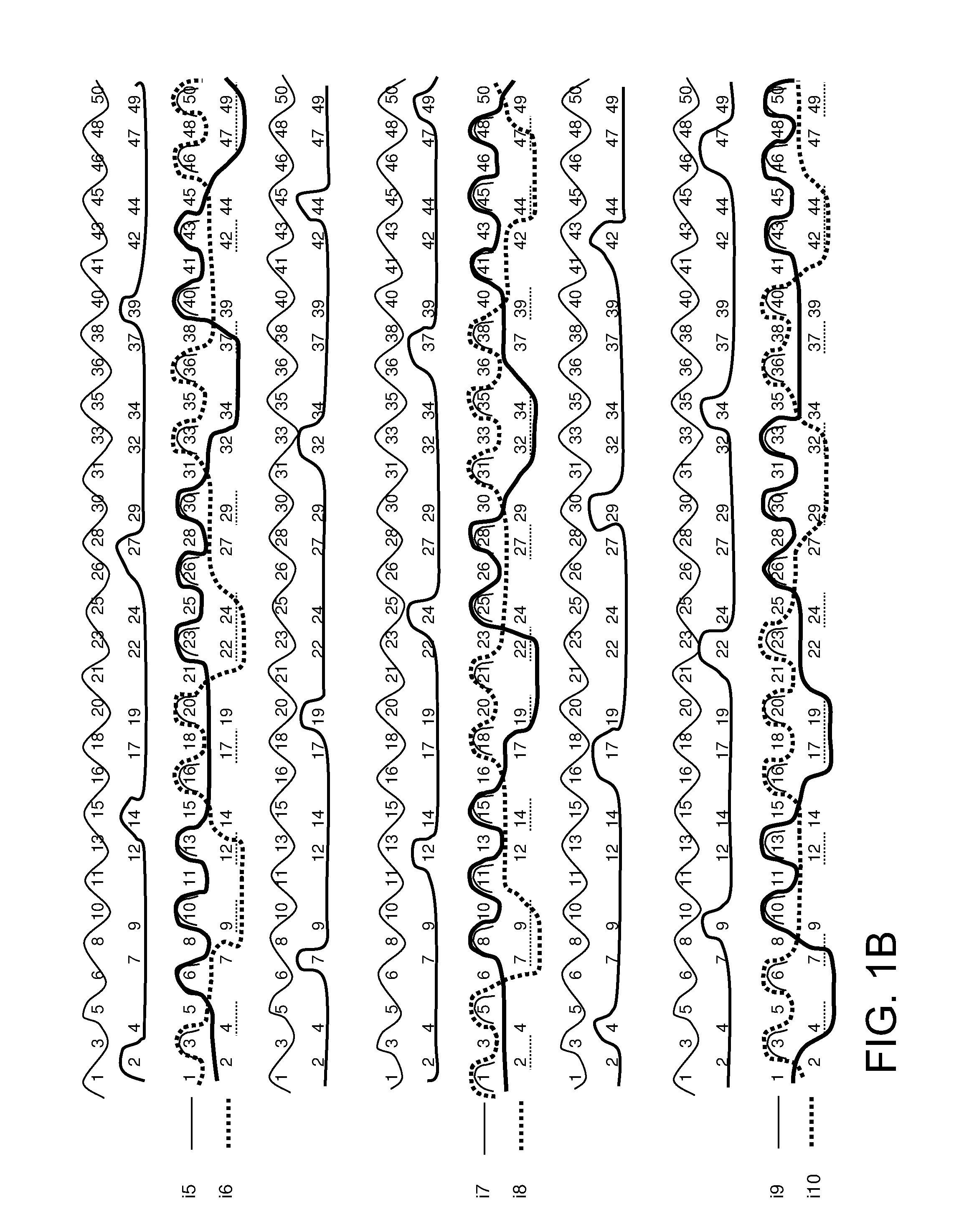
[0048]The following describes a first design example for a weave structure for a fabric belt for a machine to produce a web material, for example paper or cardboard, with reference to FIGS. 1A-1D, 2 and 3. In the examples illustrated in FIGS. 1A-1D and 2 a fabric belt of this type, for example utilized as a forming fabric, is constructed having two fabric layers 114, and 116. Here, fabric layer 114 represents a web-side, web material carrying first fabric layer. Fabric layer 116 is a machine- or operating-side second fabric layer, which comes into contact with the various rolls supporting or driving the belt. Many of the figures are on multiple pages and each figure number that is followed by a sequence of alphabetic characters denotes that the figure is continued and the weave pattern depicted is continuous even though the figure is on separate pages. A singular reference to a set of pages as a Fig. is only intended to recognize the continuity of the depicted weave pattern.

[0049]FI...


PUM


Abstract

A fabric belt for producing a web material, the fabric belt including a first layer on a web material side and a second layer on a machine side of the belt. The layers each having a basic weave connected to each other by binding threads extending in a binding thread direction. The layers having base binding threads extending both in and transverse to the binding thread direction. The binding threads form binding segments which are successive in the binding thread direction in the second layer. The binding threads are tied off on one base binding thread of the second layer extending transversely to the binding thread direction. The binding segments formed in the second layer are arranged in a binding pattern repeat extended in and transverse to the binding thread direction along a binding segment diagonal progressing obliquely to the binding thread direction and transverse to the binding thread direction.

Description

CROSS REFERENCE TO RELATED APPLICATIONS[0001]This is a continuation of PCT application No. PCT / EP2010 / 066707, entitled “FABRIC STRIP FOR A MACHINE FOR PRODUCING WEB MATERIAL, IN PARTICULAR PAPER OR CARTON”, filed Nov. 3, 2010, which is incorporated herein by reference.BACKGROUND OF THE INVENTION[0002]1. Field of the Invention[0003]The current invention relates to a fabric belt for a machine for producing a web material, in particular paper or cardboard.[0004]2. Description of the Related Art[0005]A fabric belt for a machine to produce a web material is known from WO 2008 / 068317 wherein the two fabric layers composed of the two respective basic weaves are connected with each other by binding threads which are arranged in pairs and are positioned side by side, immediately adjacent to each other. The binding threads of a respective binding thread pair alternate between the two fabric layers at respective changeover points so that they form binding segments in the paper side first fabri...

Claims


Application Information

Patent Timeline
IPC IPC(8): D21F7/08D03D3/04D21F3/02D03D11/00
CPCD21F1/0045D21F1/00D21F7/02
Inventor HOEHSL, MATTHIASBOECK, JOHANN
Owner VOITH PATENT GMBH
Learn More