Stator segment and motor

Active Publication Date: 2012-11-22
NIDEC CORP
View PDF4 Cites 32 Cited by
  • Summary
  • Abstract
  • Description
  • Claims
  • Application Information

AI Technical Summary

Benefits of technology

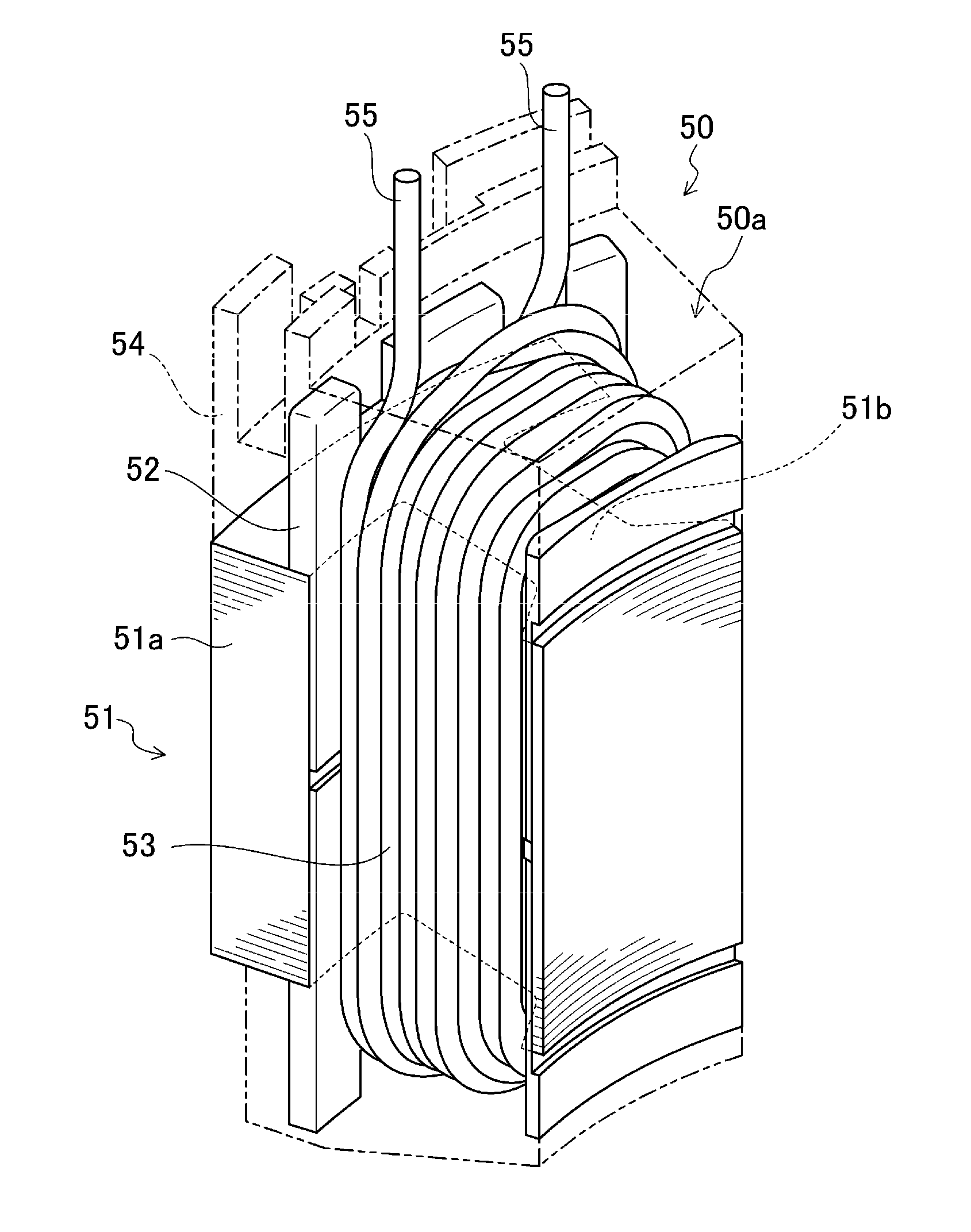
[0015]In the above-described stator segment, the circumferential end walls of the resin layer are preferably arranged circumferentially inward of circumferential end walls of the core segment. Therefore, when stator segments according to the above-described preferred embodiment of the present invention are arranged in a substantially annular shape to there

Problems solved by technology

This presents an impediment to improving productivity.
Therefore, it is difficult to a

Method used


Image

  • Stator segment and motor
  • Stator segment and motor
  • Stator segment and motor

Examples


first preferred embodiment

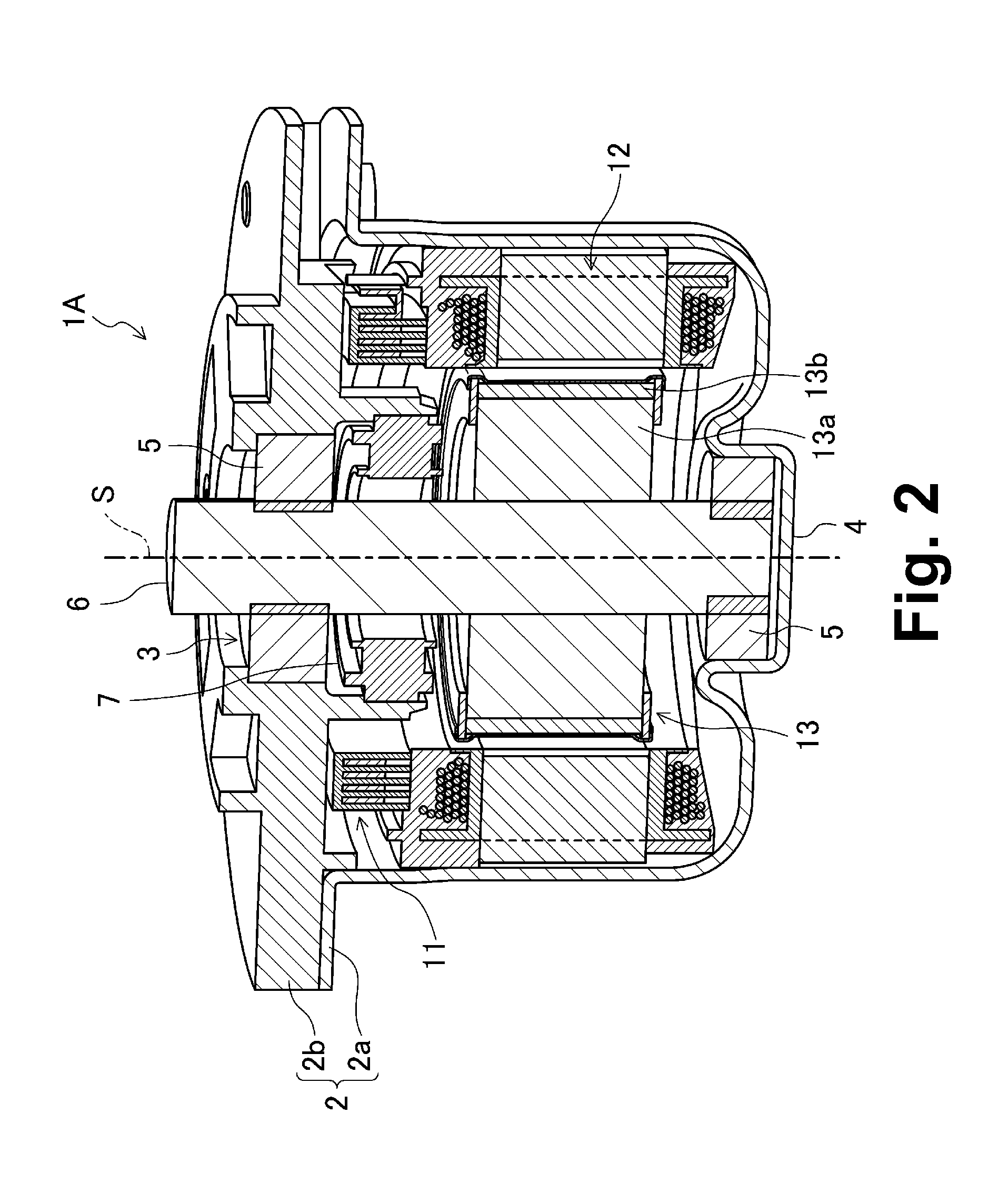
[0089]FIG. 2 illustrates a motor 1A according to a first preferred embodiment of the present invention. The motor 1A preferably is an inner-rotor brushless motor to be installed in a vehicle, and is preferably used to drive an electric power steering, for example. In particular, the motor 1A has an ability to switch between parallel connection and series-parallel connection, using the same stator. This is accomplished by attaching the passage-line busbars to the stator or removing the passage-line busbars from the stator when assembling the motor 1A.

[0090]Referring to FIG. 2, the motor 1A preferably includes a casing 2, a busbar unit 11, a stator 12, a rotor 13, a shaft 6, and so on. A center of each of the rotor 13, the stator 12, and the busbar unit 11 coincides with a center S (i.e., a rotation axis of the motor 1A) of the shaft 6.

[0091]The casing 2 preferably includes a receptacle 2a which includes a bottom and is substantially cylindrical, and a substantially disc-shaped lid 2b...

second preferred embodiment

[0150]FIG. 22 illustrates a motor 1 including a rotor 300 according to a preferred embodiment of the present invention. The motor 1 preferably is an inner-rotor brushless motor to be installed in a vehicle, and is used to drive an electric power steering, for example. As illustrated in FIG. 22, the motor 1 preferably includes a casing 2, a busbar unit 100, a stator 200, the rotor 300, a shaft 6, and so on.

[0151]The casing 2 preferably includes a receptacle 2a which has a bottom and is substantially cylindrical, and a substantially disc-shaped lid 2b. The lid 2b is preferably secured to a flange of the receptacle 2a. The flange of the receptacle 2a is preferably arranged to project radially outward around a circumference of an opening of the receptacle 2a. The stator 200 and so on are contained inside the receptacle 2a. A through hole 3 is preferably defined in a central portion of the lid 2b. A bearing portion 4 is preferably arranged on a bottom surface of the receptacle 2a to be o...


PUM


Abstract

A stator segment arranged to define a portion of an annular stator includes a core segment including a core back portion arranged to extend in a circumferential direction of the stator, and a tooth portion arranged to extend from the core back portion in a radial direction of the stator; a coil wound around the tooth portion and including a pair of coil wire terminals; an insulating layer arranged between the coil and the tooth portion; and a resin layer arranged to seal the entire coil except for the pair of coil wire terminals. Circumferential end walls of the resin layer are arranged circumferentially inward of circumferential end walls of the core back portion.

Description

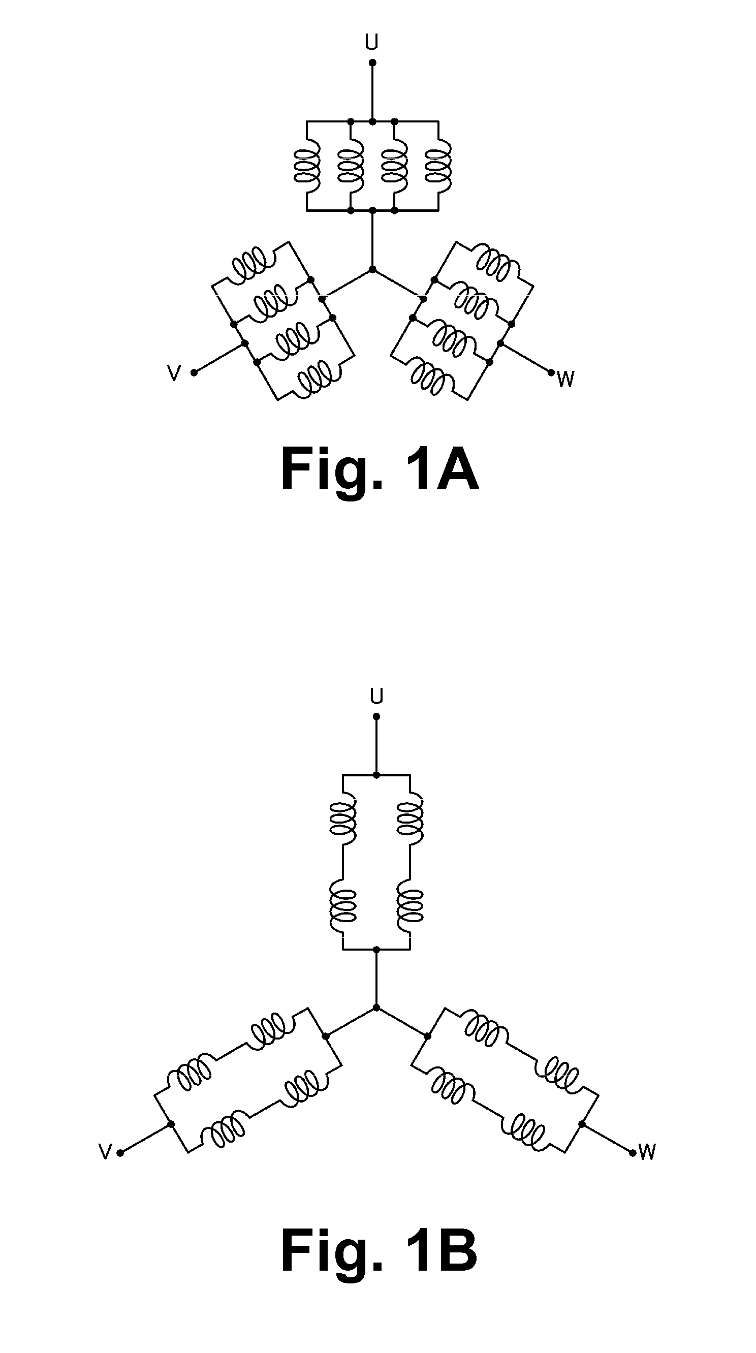
BACKGROUND OF THE INVENTION[0001]1. Field of the Invention[0002]The present invention relates to an inner-rotor motor in which a stator includes a plurality of stator segments. In particular, the present invention relates to a wiring configuration of a stator.[0003]2. Description of the Related Art[0004]In general, motors have a variety of potential performance levels that are varied depending on the intended purposes of the motors. The number of poles of a rotor, the number of slots of the stator, the direction of the winding of coils, the arrangement of the coils, and so on are designed in accordance with a desired performance of the motor. Thus, there are a large variety of wiring configurations available for motors.[0005]For instance, referring to FIG. 1A, in an 8-pole 12-slot motor, a group of four coils connected in parallel may be provided for each of a U phase, a V phase, and a W phase. Moreover, the groups of coils for the respective phases may be connected in a Y configura...

Claims


Application Information

Patent Timeline
IPC IPC(8): H02K3/32
CPCH02K1/148H02K1/278H02K3/28H02K3/522H02K5/225H02K3/32H02K15/095H02K15/12H02K2203/09H02K2203/12H02K15/03
Inventor YOKOGAWA, TOMOYOSHINAKAGAWA, AIRI
Owner NIDEC CORP
Why Eureka
Try Eureka