Vehicle surroundings monitoring device

a monitoring device and vehicle technology, applied in scene recognition, television systems, instruments, etc., can solve the problems of reliability of the photographed image of the camera, the accuracy of the classification determination of the physical body drops, and the reliability of the classification determination of the physical body drops, so as to prevent the accuracy of the classification determination of the physical body

Active Publication Date: 2012-11-22
HONDA MOTOR CO LTD
View PDF2 Cites 19 Cited by
  • Summary
  • Abstract
  • Description
  • Claims
  • Application Information

AI Technical Summary

Benefits of technology

[0023]According to the present invention, in the case where the detected position of the reflector in the physical body periodically changes, it may be assumed that the reflectors of the pedals displacing vertically by the pedaling operation of the pedals by the rider of the bicycle are detected. Therefore, in this case, the classification determining unit may determine that the physical body detected by the radar is the bicycle. And, in this case, the determination of whether or not the physical body is the bicycle is performed without using the photographed image by the camera, so that it becomes possible to prevent the classification determination accuracy of the physical body from dropping, in the case where the reliability of the photographed image by the camera drops from the influence of the environment.

Problems solved by technology

As is explained above, in the case where the type of the detected physical body is determined on the basis of the distance to the physical body detected by the radar and the image of the physical body imaged by the camera, there is an inconvenience that the reliability of the photographed image of the camera drops and the accuracy of the classification determination of the physical body drops, when receiving backlight in nighttime, in bad weather and the like.
Further, in the case where an infrared camera is used, there is an inconvenience that the reliability of the classification determination of the physical body drops, by the decrease in the contrast of the photographed image during severe heat.

Method used


Image

  • Vehicle surroundings monitoring device
  • Vehicle surroundings monitoring device
  • Vehicle surroundings monitoring device

Examples


Embodiment Construction

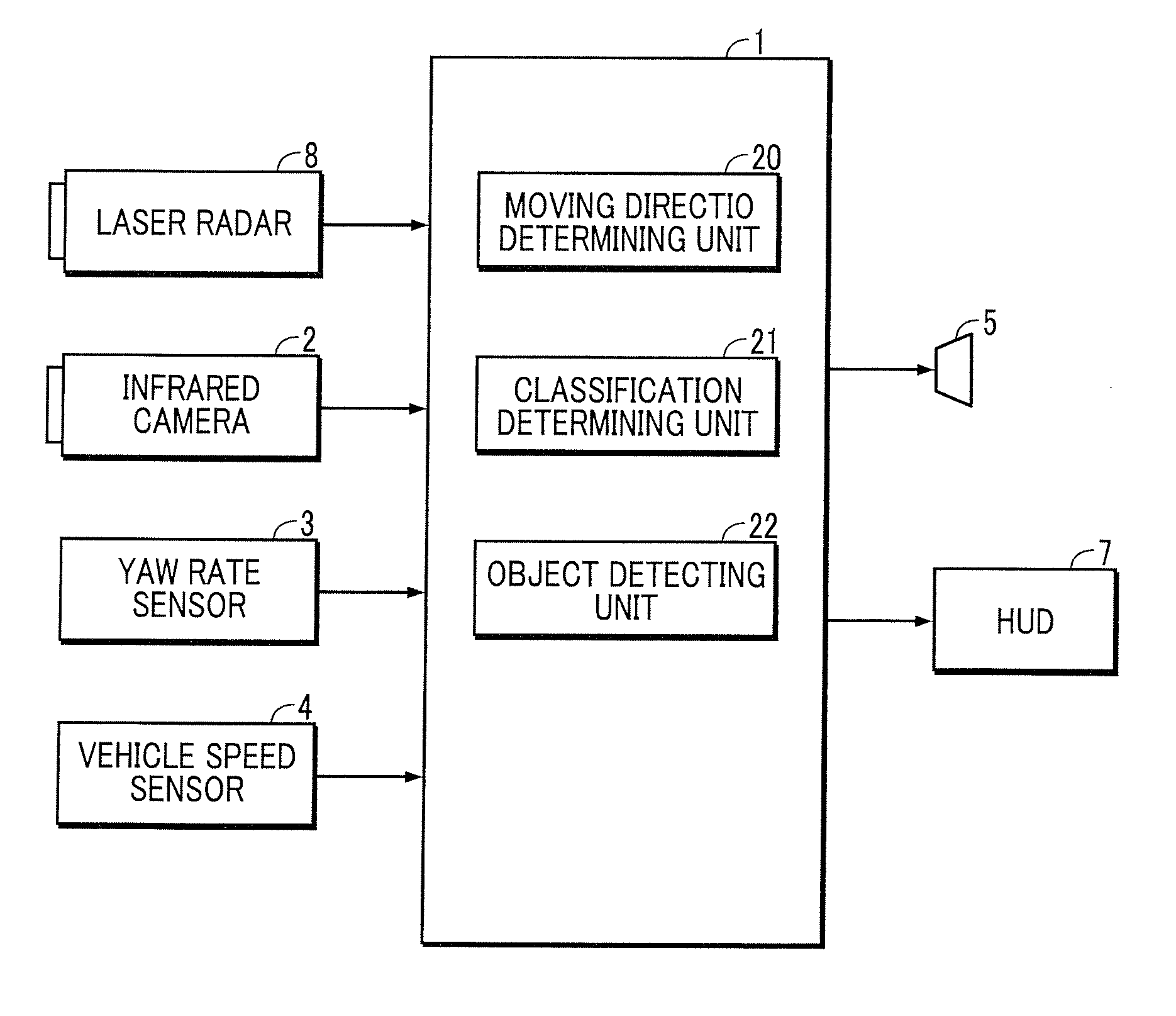
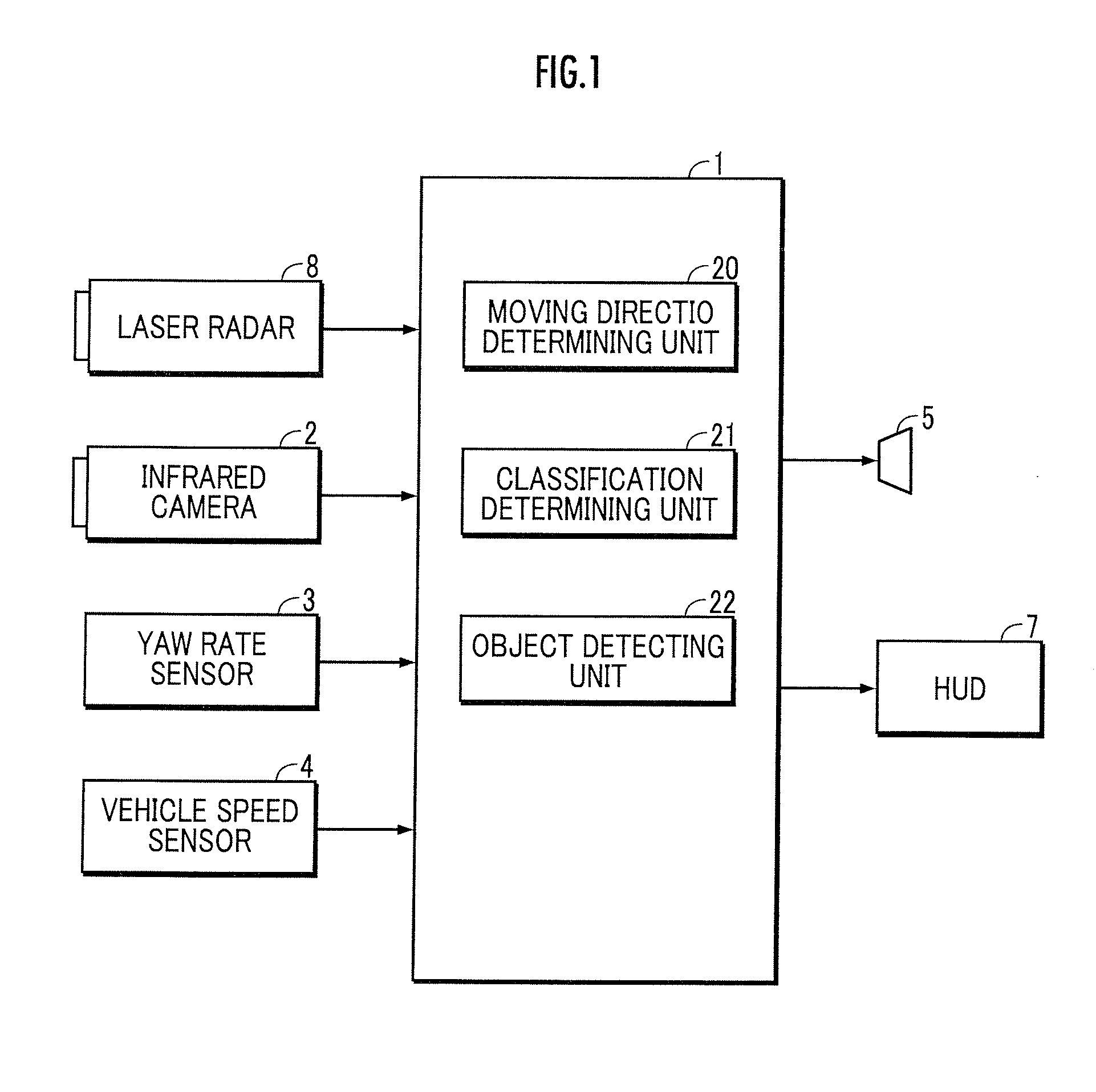
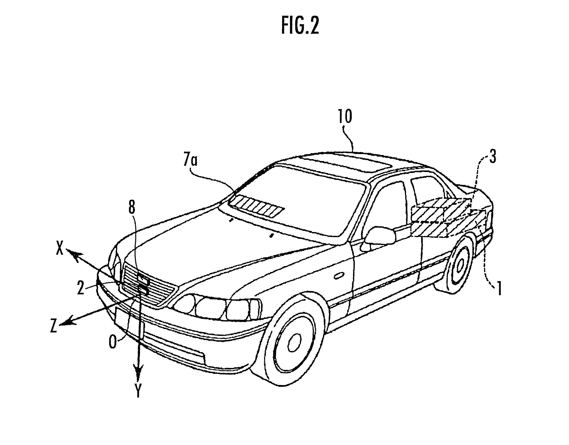
[0032]An embodiment of the present invention will be explained with reference to FIG. 1 through FIG. 8. Referring to FIG. 1, the vehicle surroundings monitoring device of the present invention is equipped with an ECU (Electronic Control Unit) 1, an infrared camera (corresponds to the camera of the present invention) capable of detecting far infrared ray, a laser radar 8 (corresponds to the radar of the present invention) which detects a relative position (includes relative distance) between a physical body and a vehicle in real space by irradiating laser light to the physical body and receiving a reflected wave therefrom, a yaw rate sensor 3 which detects a yaw rate of the vehicle, and a vehicle speed sensor 4 which detects a traveling speed of the vehicle.

[0033]The ECU 1 discriminates a classification of the physical body (four-wheel vehicle, two-wheel vehicle, bicycle, pedestrian, and the like) existing in front of the vehicle from a detection data of the position of the physical ...


PUM


Abstract

A vehicle surroundings monitoring device includes a moving direction determining unit 20 which determines whether a physical body is moving in a traveling direction of a self vehicle or a transverse direction orthogonal to the traveling direction, from a change in a detection position of the physical body by a laser radar 8, wherein a classification determining unit 21 executes a first classification determining process of determining the physical body determined to be moving in the traveling direction as a four-wheel vehicle when dimensions of the physical body obtained from the detected position by the laser radar 8 is within a range of A1, and a second classification determining process of determining the physical body determined to be moving in the transverse direction as the four-wheel vehicle when the dimensions of the physical body obtained from the detected position by the laser radar 8 is within a range of B1.

Description

BACKGROUND OF THE INVENTION[0001]1. Field of the Invention[0002]The present invention relates to a vehicle surroundings monitoring device which recognizes a physical body existing in the surroundings of a vehicle, using position information of the physical body by a radar mounted on the vehicle and a photographed image by a camera mounted on the vehicle.[0003]2. Related Background Art[0004]Conventionally, there is proposed a physical body detecting device in which a vehicle is mounted with a radar and a camera, and the physical body detecting device determines a type of the detected physical body on the basis of the distance to the physical body detected by the radar and the image of the physical body imaged by the camera (for example, refer to Patent Document 1).[0005]The physical body detecting device disclosed in Patent Document 1 calculates a relative velocity between a self vehicle and the physical body from the change in the distance to the physical body detected by the radar,...

Claims


Application Information

Patent Timeline
Patent Type & Authority Applications(United States)
IPC IPC(8): G01S13/93G01S13/86G01S17/931G01S13/931G01S17/86
CPCG01S17/023G01S17/936G06K2209/23G08G1/166G06K9/00805H04N5/33G08G1/015G08G1/167G01S17/58G01S17/86G01S17/931G06V20/58G06V2201/08G01S13/589G01S13/931G01S7/415G01S2013/93271G01S13/867G01S2013/9323
Inventor NISHIGAKI, MORIMICHIYOKOCHI, YUJIEGUCHI, ATSUHIRONEGORO, MASAKISAWADA, KENICHI
Owner HONDA MOTOR CO LTD
Why Eureka
Try Eureka