Touch screen device and plasma display apparatus having the same

plasma display technology, applied in the direction of instruments, computing, electric digital data processing, etc., can solve the problems of integrating an image display apparatus with a touch screen device, noise substantially affecting the accuracy of detecting a touch position, and is susceptible to exogenous noise, so as to reduce the detection accuracy of a touch position

Inactive Publication Date: 2012-11-22
PANASONIC INTELLECTUAL PROPERTY MANAGEMENT CO LTD
View PDF3 Cites 22 Cited by
  • Summary
  • Abstract
  • Description
  • Claims
  • Application Information

AI Technical Summary

Benefits of technology

[0012]According to the present invention, the drive signal is generated from the reference signal and has the same frequency and phase as the reference signal. Thus, the response signal is output from the receiving electrode with the same frequency and phase as the reference signal. Furthermore, the reference signal is used to preform synchronized detection of a signal based on the response signal from the receiving electrode. Thereby, noise having a different frequency from the reference signal is removed and only a signal value for the response signal from the receiving electrode having the same frequency as the reference signal is obtained. This prevents a reduction in detection accuracy of a touch position due to exogenous noise.

Problems solved by technology

In a configuration where numerous electrodes are provided in a panel, such as in resistive and capacitance types, the electrodes act as antennas, and are thus susceptible to exogenous noise.
Thus, noise substantially affects accuracy in detecting a touch position.
Integrating an image display apparatus with a touch screen device reduces accuracy in detecting a touch position due to noise caused by the image display apparatus.
Due to substantial radiated noise associated with discharge of a plasma display panel, however, the conventional noise reduction measure does not sufficiently solve the noise issue and substantially reduces the accuracy in detecting a touch position, and is thus incapable of ensuring sufficient detection accuracy in practice.[Related Art 1] Japanese Patent Laid-open Publication No.

Method used


Image

  • Touch screen device and plasma display apparatus having the same
  • Touch screen device and plasma display apparatus having the same
  • Touch screen device and plasma display apparatus having the same

Examples


Embodiment Construction

[0027]The particulars shown herein are by way of example and for purposes of illustrative discussion of the embodiments of the present invention only and are presented in the cause of providing what is believed to be the most useful and readily understood description of the principles and conceptual aspects of the present invention. In this regard, no attempt is made to show structural details of the present invention in more detail than is necessary for the fundamental understanding of the present invention, the description taken with the drawings making apparent to those skilled in the art how the forms of the present invention may be embodied in practice.

[0028]An embodiment of the present invention is explained below with reference to the drawings.

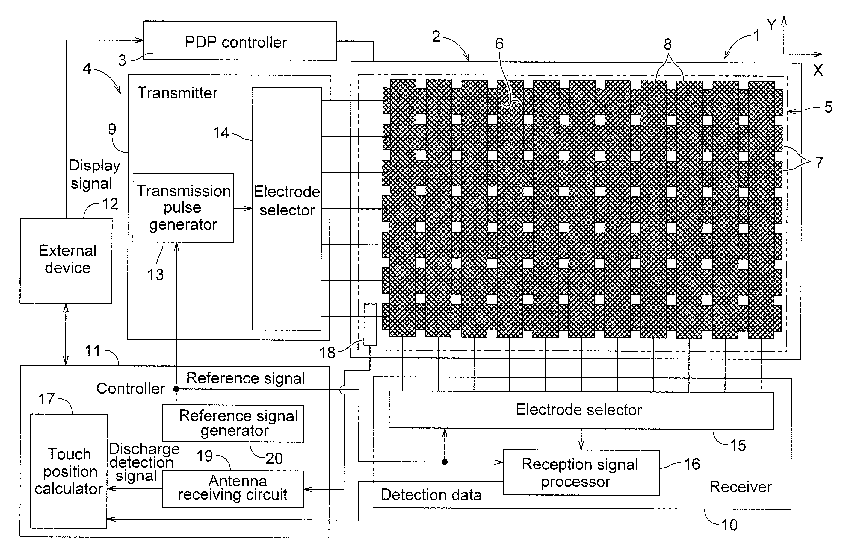
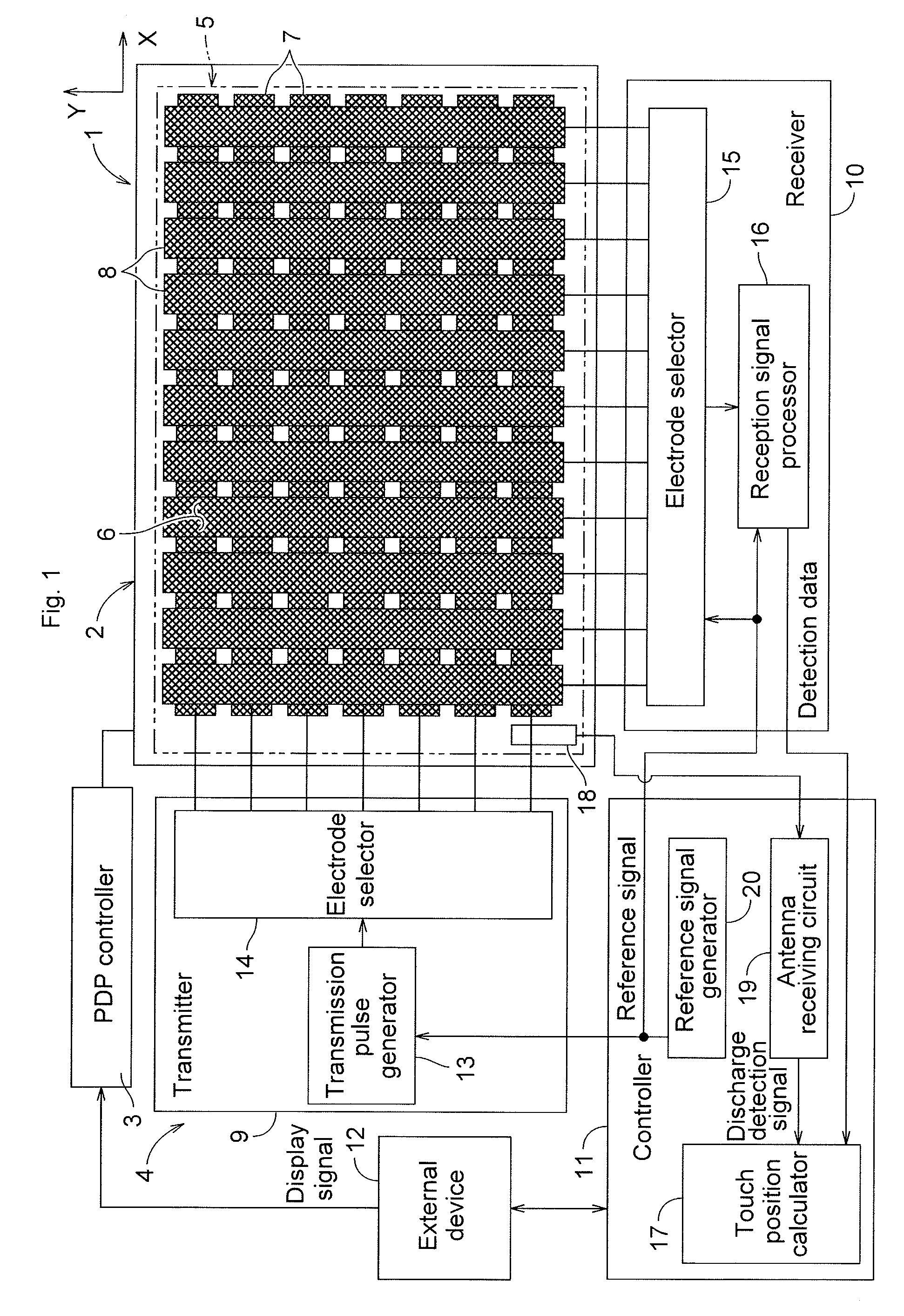
[0029]FIG. 1 illustrates an overall configuration of a plasma display apparatus 1 according to the present embodiment. The plasma display apparatus 1 has a plasma display panel (hereinafter referred to as PDP) 2, a PDP controller 3, and...


PUM


Abstract

A touch screen device has a screen main body including parallel transmitting electrodes and parallel receiving electrodes disposed in a grid shape; a transmitter sequentially selecting the transmitting electrodes and applying a drive signal; a receiver sequentially selecting the receiving electrodes, receiving a response signal output from the receiving electrode in response to the drive signal, and outputting detection data at each electrode intersection; a controller obtaining a touch position based on the detection data at each electrode intersection output from the receiver; and a reference signal generator outputting a reference signal for synchronized detection. The transmitter generates the drive signal from the reference signal. The receiver uses the reference signal to perform synchronized detection of a signal based on the response signal from the receiving electrode and generates the detection data.

Description

CROSS-REFERENCE TO RELATED APPLICATIONS[0001]The present application claims priority under 35 U.S.C. §119 of Japanese Application No. 2011-112051 filed on May 19, 2011, the disclosure of which is expressly incorporated by reference herein in its entirety.BACKGROUND OF THE INVENTION[0002]1. Field of the Invention[0003]The present invention relates to a touch screen device that detects a touch position by a capacitance method and a plasma display apparatus having the touch screen device.[0004]2. Description of Related Art[0005]There are various methods, based upon different principles, for a touch screen device to detect a touch position. In a configuration where numerous electrodes are provided in a panel, such as in resistive and capacitance types, the electrodes act as antennas, and are thus susceptible to exogenous noise. In the capacitance type, in particular, a touch position is detected from a minor variation in capacitance proximate to electrodes caused by the approach or cont...

Claims


Application Information

Patent Timeline
Patent Type & Authority Applications(United States)
IPC IPC(8): G06F3/041G09G3/28
CPCG06F3/044G06F3/0446G06F3/0445
Inventor KITADA, TAKASHI
Owner PANASONIC INTELLECTUAL PROPERTY MANAGEMENT CO LTD
Why Eureka
Try Eureka