System and method of revising depth of a 3D image pair

Active Publication Date: 2012-11-22
NAT TAIWAN UNIV +1
View PDF6 Cites 81 Cited by
  • Summary
  • Abstract
  • Description
  • Claims
  • Application Information

AI Technical Summary

Benefits of technology

[0009]In view of the foregoing, it is an object of the embodiment of the present invention to provide a syst

Problems solved by technology

However, for the conventional 3D imaging system 2, there are still some basic constraints in stereo videos, such as occlusion, two-camera setting parameter deviation, which may affec

Method used


Image

  • System and method of revising depth of a 3D image pair
  • System and method of revising depth of a 3D image pair
  • System and method of revising depth of a 3D image pair

Examples


Embodiment Construction

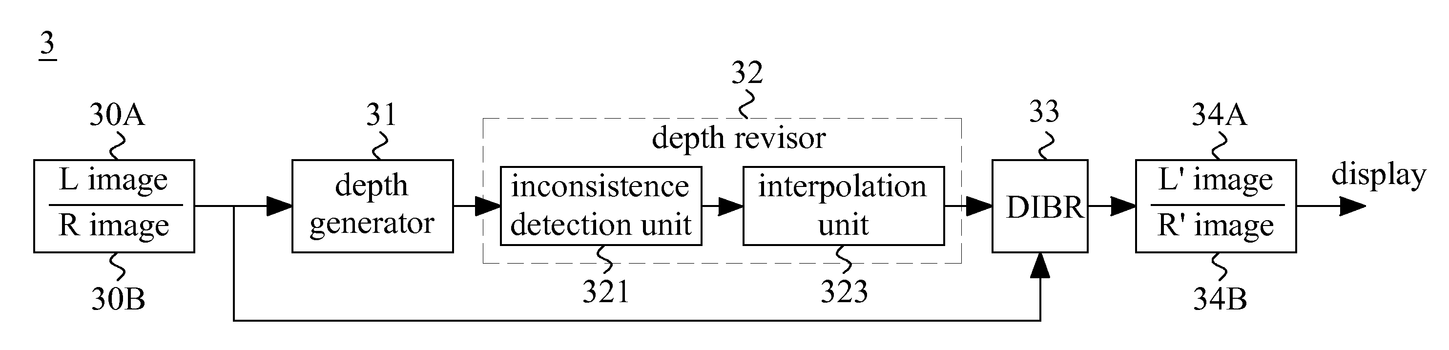
[0017]FIG. 3 shows a block diagram illustrating a system of revising depth of a three-dimensional (3D) image pair according to one embodiment of the present invention. The 3D image pair is also called a stereoscopic image. The system 3 comprises a depth generator 31, a depth revisor 32 and a depth-image-based rendering (DIBR) unit 33. The depth generator 31 receives a left (L) image 30A and a right (R) image 30B, which are the 3D image pair, displayable in a 3D imaging system to generate at least one depth map. For example, the depth generator 31 may generate a left depth map and a right depth map that correspond to the original left image 30A and the right image 30B based on stereo matching technique respectively.

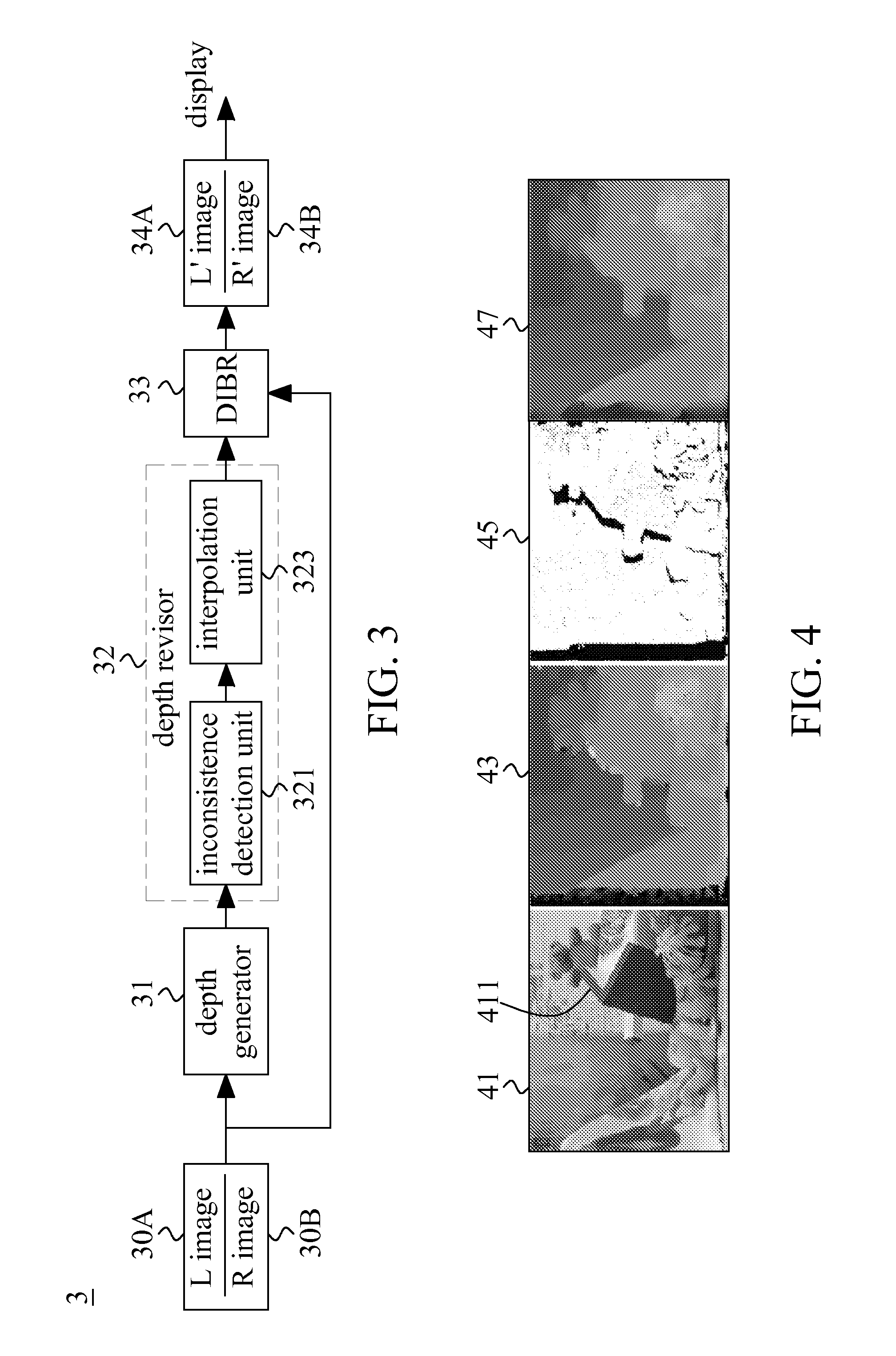
[0018]In order to facilitate explaining, take a single depth map for example as follows. Please refer to FIG. 4 as well. The depth generator 31 generates an initial depth map 43 associated with one image 41 (e.g., the left image 30A or the right image 30B) of the 3D image ...


PUM


Abstract

A method of revising depth of a three-dimensional (3D) image is disclosed. The method comprises the following steps: firstly, at least one initial depth map associated with one image of the 3D image pair based on stereo matching technique is received, wherein the one image comprises a plurality of pixels, and the initial depth map carries an initial depth value of each pixel. Then, the inconsistence among the pixels of the one image of the 3D image pair is detected to estimate a reliable map. Finally, the initial depth value is interpolated according to the reliable map and the proximate pixels, so as to generate a revised depth map by revising the initial depth value.

Description

BACKGROUND OF THE INVENTION[0001]1. Field of the Invention[0002]The present invention generally relates to digital image processing, and more particularly to a system and method of revising depth generated based on a three-dimensional (3D) image pair.[0003]2. Description of Related Art[0004]When three-dimensional (3D) objects are mapped onto a two-dimensional (2D) image plane by prospective projection, such as an image taken by a still camera or a video camera, a lot of information, particularly 3D depth information, disappears. A 3D imaging system, however, can convey 3D information to a viewer by recording 3D visual information or by re-creating the illusion of depth. Although the 3D imaging technique has been known for over a century, the 3D display becomes more practical and popular owing to availability of high-resolution and low-price displays such as liquid crystal displays (LCDs).[0005]FIG. 1 shows a block diagram of a conventional 3D imaging system 1 that creates depth info...

Claims


Application Information

Patent Timeline
IPC IPC(8): H04N13/02
CPCH04N13/0022H04N13/128
Inventor CHEN, LIANG-GEEWU, CHIENLI, CHUNG-TELAI, YEN-CHIEHCHENG, CHAO-CHUNGHUANG, LING-HSIU
Owner NAT TAIWAN UNIV
Why Eureka
Try Eureka