
Image forming apparatus, image forming system, image forming system control method, and program

a technology of image forming and control method, applied in the direction of digital output to print unit, visual presentation, instruments, etc., can solve the problems of reducing user convenience, restricting printing, and unable to retransmit and print data to the receiver

Active Publication Date: 2012-11-22
CANON KK
View PDF6 Cites 16 Cited by
  • Summary
  • Abstract
  • Description
  • Claims
  • Application Information

AI Technical Summary

Benefits of technology

The present invention is about controlling printing based on the type of data received via a network. It includes a receiving unit for receiving data, a printing unit for printing an image, and a control unit for controlling the receiving unit. The control unit can refuse to receive data if the printing unit has low toner remaining amount. However, if the receiving unit receives page description language (PDL) data, the printing unit can still print the image even if the toner remaining amount is low. This invention allows for suitable restriction of image formation based on the type of data received via a network.

Problems solved by technology

When printing the received PDL data, although printing can be repeated by re-transmitting the data from the PC, if the received data is electronic mail data, since the sender and the receiver are different, in many cases it is impossible for the receiver to re-transmit and print the data.
Consequently, if printing is prohibited across the board regardless of the type of data when the toner remaining amount falls below the predetermined value as carried out in the conventional method, when receiving and printing the print data, printing is restricted despite the fact that a few pages can be printed even though the toner remaining amount has fallen below the predetermined value.
Consequently, user convenience is dramatically reduced.

Method used


Image

  • Image forming apparatus, image forming system, image forming system control method, and program
  • Image forming apparatus, image forming system, image forming system control method, and program
  • Image forming apparatus, image forming system, image forming system control method, and program

Examples


Embodiment Construction

[0022]Various exemplary embodiments, features, and aspects of the invention will be described in detail below with reference to the drawings.

[0023]An embodiment of the present invention will now be described using the drawings.

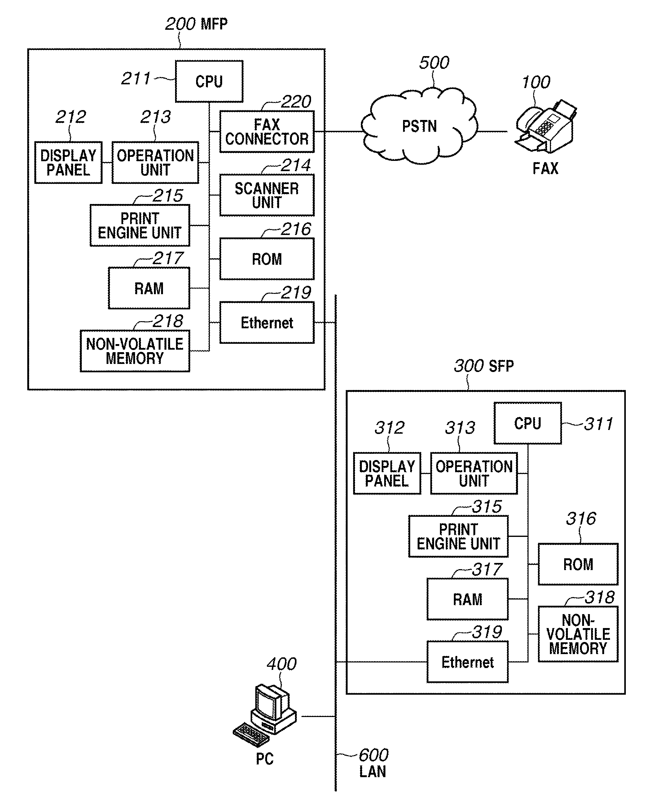
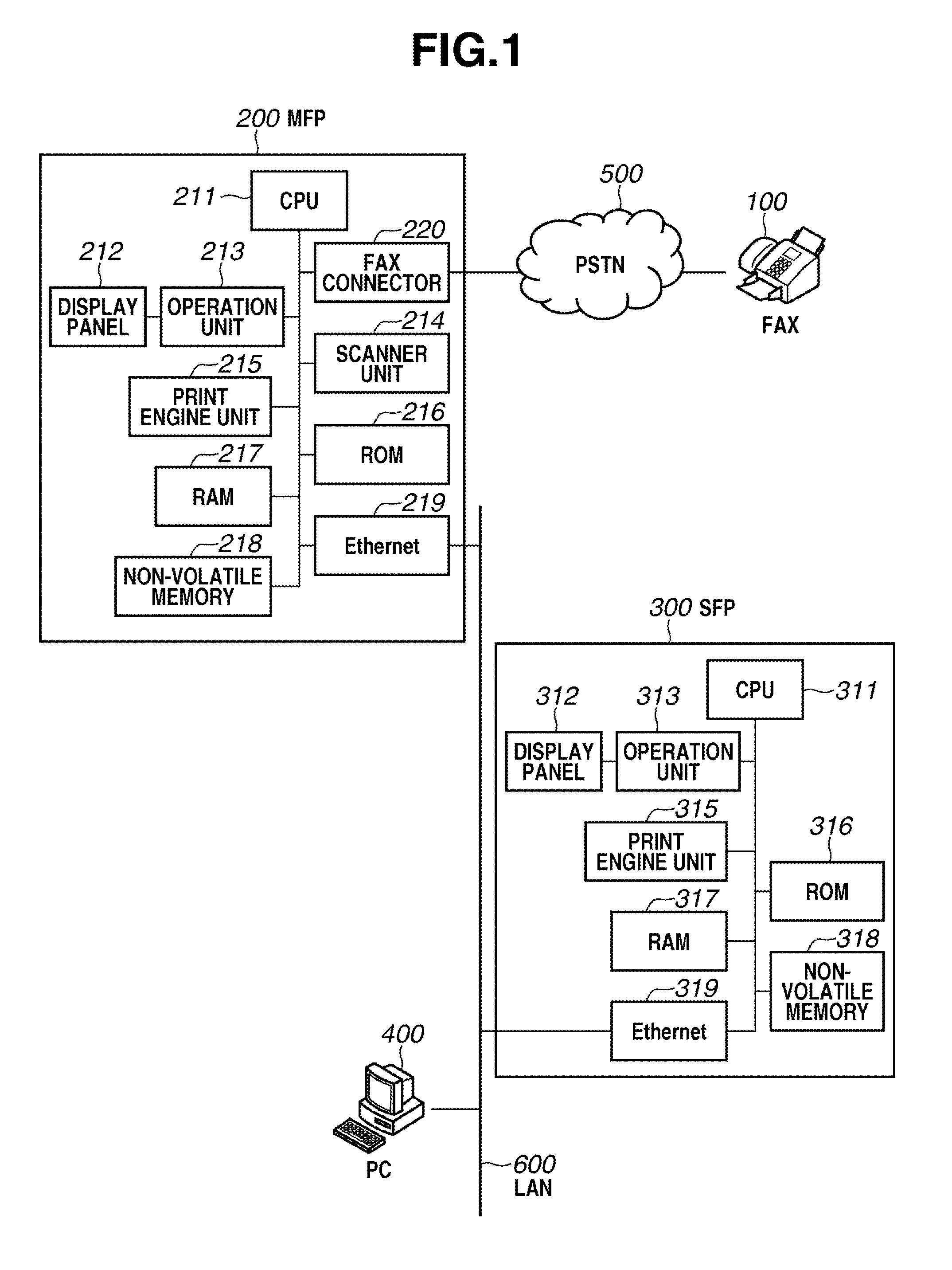
[0024]FIG. 1 is a block diagram illustrating a configuration of an image forming system according to the present embodiment. This image forming system is configured from a facsimile apparatus 100 (hereinafter, “FAX apparatus”) for transmitting facsimile data, an MFP 200 that includes a plurality of functions, such as a facsimile function, a print function, and an E-mail transmission function, a single function apparatus (hereinafter, “SFP”) 300 for printing, and a versatile personal computer (hereinafter, “PC”) 400. In the present embodiment, the MFP is described as an example of a data communication apparatus, and the SFP is described as an example of an image forming apparatus.

[0025]The FAX apparatus 100 and the MFP 200 are connected by a public switched tel...


PUM


Abstract

An image forming apparatus includes a receiving unit configured to receive data via a network, a printing unit configured to print an image based on the data received from the receiving unit, and a control unit configured to control the receiving unit to refuse a data reception based on a simple mail transfer protocol (SMTP) when a toner remaining amount for the printing unit is less than a predetermined value, wherein the printing unit is configured to print, in the case that the receiving unit receives page description language (PDL) data, an image based on the received PDL data even if the toner remaining amount is less than the predetermined value.

Description

BACKGROUND OF THE INVENTION[0001]1. Field of the Invention[0002]The present invention relates to an image forming system configured from a data communication apparatus that transmits electronic mail data generated based on facsimile data received via a public line and an image forming apparatus that forms an image based on that electronic mail data.[0003]2. Description of the Related Art[0004]Conventionally, an image forming apparatus that has a facsimile function for transmitting and receiving facsimile data via a public line has been generally known. Further, in recent years Internet facsimile apparatuses (hereinafter sometimes also referred to as “Internet FAX apparatus”) have been also becoming commonplace as a facsimile apparatus capable of performing facsimile communication via the Internet using an electronic mail protocol. An Internet FAX transmits data by using an electronic mail protocol (simple mail transfer protocol (“SMTP”)) instead of a telephone line, and is recommend...

Claims


Application Information

Patent Timeline
Patent Type & Authority Applications(United States)
IPC IPC(8): G06K15/02
CPCH04N1/00915H04N1/3247H04N1/2346H04N1/00917G06F3/1296H04N1/00209H04N1/32635H04N1/32673H04N2201/0082H04N2201/0093H04N1/00204H04N2201/3226H04N1/001H04N1/32021H04N2201/0094H04N2201/0024G06K15/00
Inventor HIRAIKE, KOU
Owner CANON KK
Learn More