Vehicle lighting unit

a technology for vehicle lighting and lighting components, applied in the direction of vehicle components, lighting and heating apparatus, lighting device details, etc., can solve the problems of deteriorating the usefulness of semiconductor laser light sources as light sources, color unevenness in light distribution patterns, etc., to ensure the usefulness of semiconductor laser light sources, reduce the coherence of excitation light, suppress the color uneven light distribution patterns

Active Publication Date: 2012-11-22
STANLEY ELECTRIC CO LTD
View PDF8 Cites 25 Cited by
  • Summary
  • Abstract
  • Description
  • Claims
  • Application Information

AI Technical Summary

Benefits of technology

[0013]According to the presently disclosed subject matter, part of the excitation light that is emitted from the semiconductor laser light source and reflected off the surface of the wavelength conversion material can be incident on the reflector with a wide area in the right-to-left direction. This excitation light that is reflected can be diffused by the reflector wider in the right-to-left direction than in the vertical direction. This configuration can reduce the coherency of the excitation light. Furthermore, while the color (for example, blue) of the excitation light can be thinned down, the excitation light can exit from the vehicle lighting unit. Therefore, the vehicle lighting unit can suppress the color unevenness of the light distribution pattern while ensuring the usefulness of the semiconductor laser light source.

Problems solved by technology

That part of light may exit from the vehicle lighting unit without color mixture, thereby generating color unevenness in the light distribution pattern formed by the vehicle lighting unit.
Therefore, if the power density thereof is made larger than the maximum permission exposure, deterioration of the usefulness of the semiconductor laser light source as a light source may occur.

Method used


Image

  • Vehicle lighting unit
  • Vehicle lighting unit
  • Vehicle lighting unit

Examples


Embodiment Construction

[0028]A description will now be made below to vehicle lighting units of the presently disclosed subject matter with reference to the accompanying drawings and in accordance with exemplary embodiments.

[0029]Herein, unless otherwise specified, the front, rear (back), left, right, up and down can be used as respective directions when the vehicle lighting unit is installed on a vehicle body with respect to the directions of the vehicle body, and correspond to the directions in the drawings.

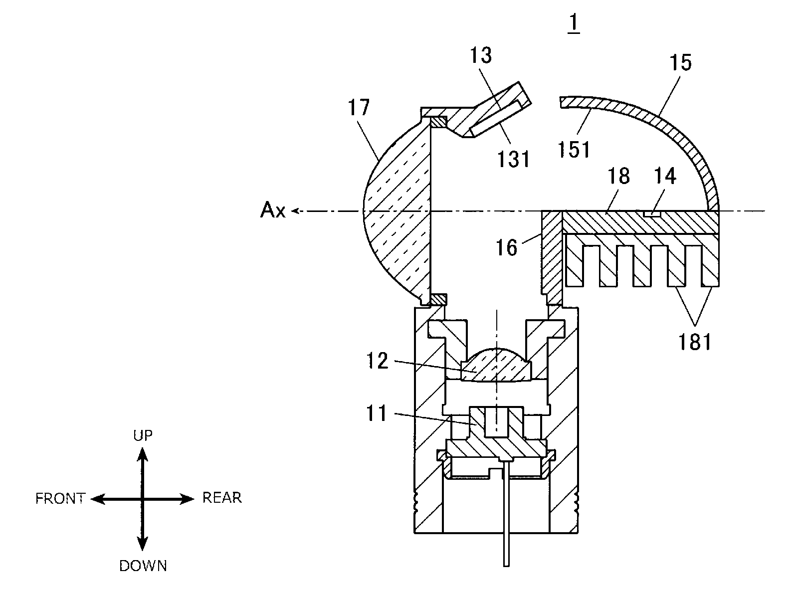
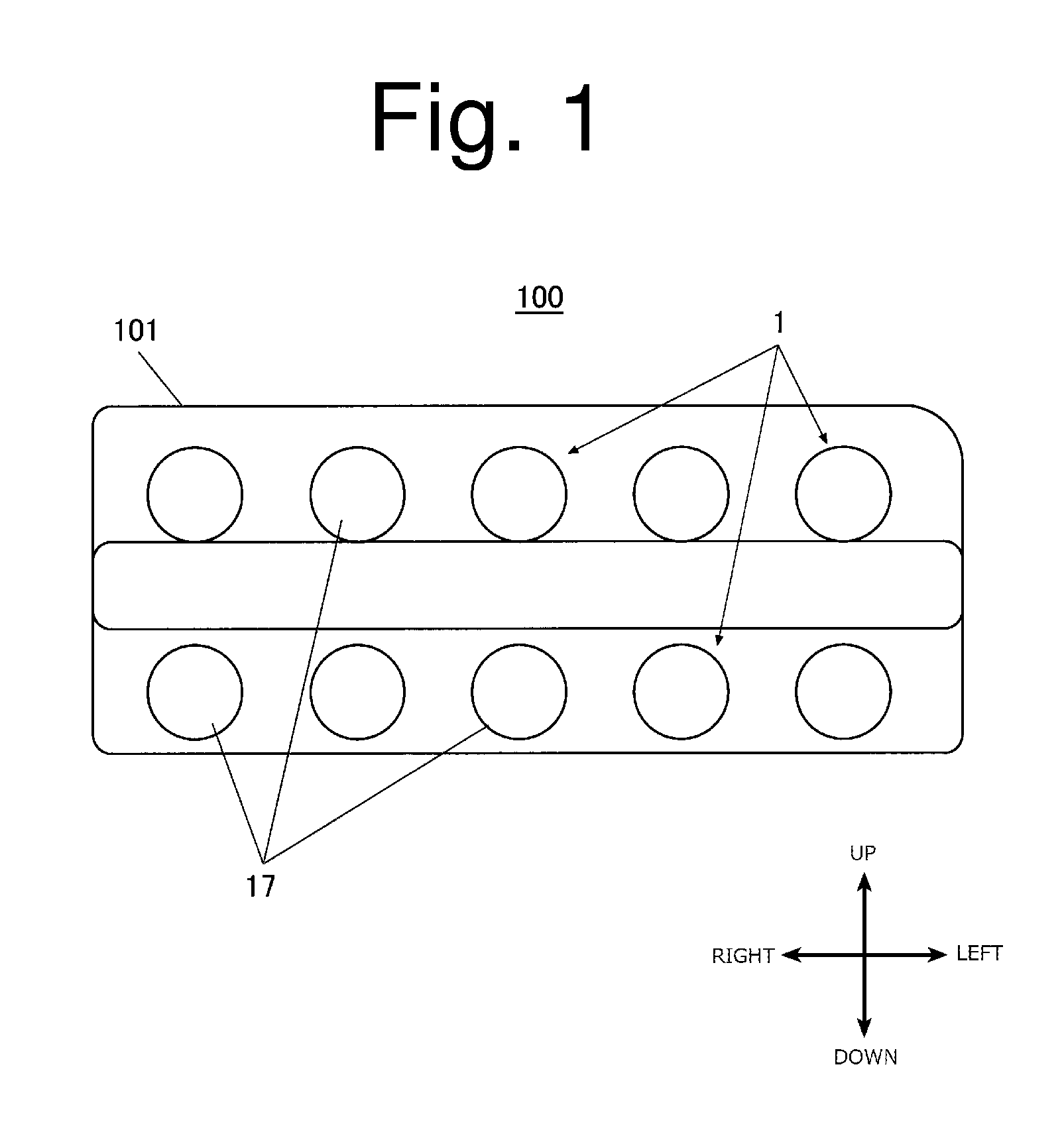
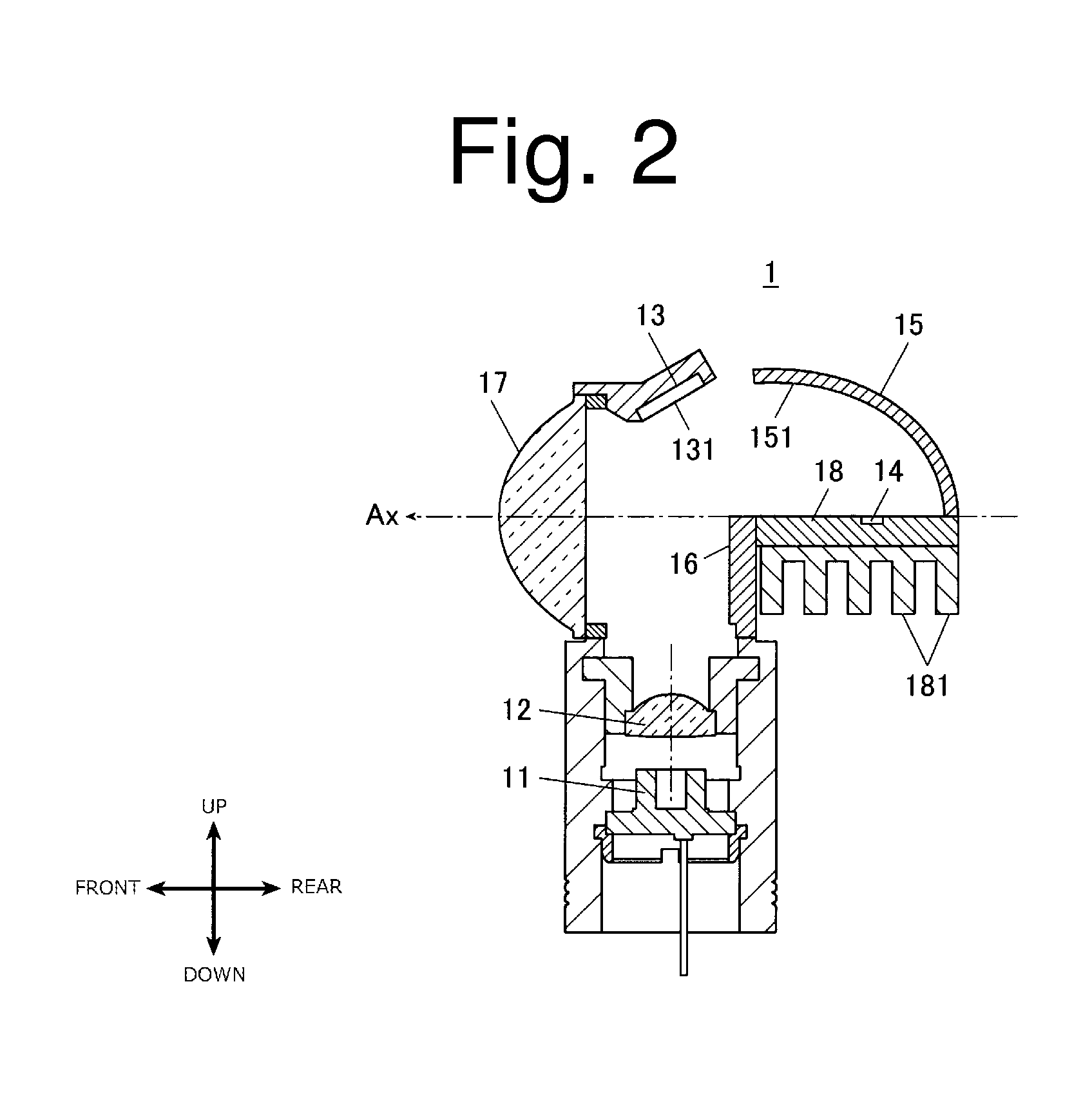
[0030]FIG. 1 is a front view of a vehicle headlamp 100 containing vehicle lighting units 1 according to a first exemplary embodiment made in accordance with principles of the presently disclosed subject matter. FIG. 2 is a cross-sectional side view of the vehicle lighting unit 1.

[0031]As shown in FIG. 1, the vehicle headlamp 100 can include a plurality of the vehicle lighting units 1 in a lighting chamber covered with a transparent cover 101 at its front side. The plurality of vehicle lighting units 1...


PUM


Abstract

A vehicle lighting unit that utilizes a semiconductor laser light source can suppress color unevenness of a light distribution pattern while ensuring the usefulness of the semiconductor laser light source. The vehicle lighting unit can include a semiconductor laser light source, a phosphor configured to receive blue light emitted from the semiconductor laser light source and emit white light by excitation, and a reflector configured to reflect the light emitted from the phosphor so that the light can be diffused wider in a right-to-left direction than in a vertical direction on the basis of a posture when the lighting unit is mounted on a vehicle body. Part of the blue light that is emitted from the semiconductor laser light source and reflected off a surface of the phosphor can be incident on the reflector with an elongated area in the right-to-left direction.

Description

[0001]This application claims the priority benefit under 35 U.S.C. §119 of Japanese Patent Application No. 2011-111958 filed on May 19, 2011, which is hereby incorporated in its entirety by reference.TECHNICAL FIELD[0002]The presently disclosed subject matter relates to a lighting device, such as a vehicle lighting unit.BACKGROUND ART[0003]As one type of conventional vehicle lighting units such as a vehicle headlamp, a lighting unit utilizing a semiconductor light emitting element as a light source together with a wavelength conversion material such as a phosphor has been known (see, for example, Japanese Patent No. 4124445). With this type of vehicle lighting unit, the semiconductor light emitting element can emit light such as blue light, so that the phosphor can be irradiated with the blue light. Therefore, the phosphor can be excited to emit light such as yellow light. The blue light originated from the semiconductor light emitting element and the yellow light from the phosphor ...

Claims


Application Information

Patent Timeline
Patent Type & Authority Applications(United States)
IPC IPC(8): F21V13/14F21V13/08
CPCF21S48/1104F21S48/1159F21S48/1195F21S48/1388F21S48/1335F21S41/135F21S41/16F21S41/176F21S41/19F21S41/285F21S41/321F21S41/323F21S41/365F21S45/47F21S41/125F21S41/18
Inventor NAKAZATO, YOSHIAKI
Owner STANLEY ELECTRIC CO LTD
Why Eureka
Try Eureka