Image processor and image processing method

Active Publication Date: 2011-11-24
CANON KK
View PDF4 Cites 8 Cited by
  • Summary
  • Abstract
  • Description
  • Claims
  • Application Information

AI Technical Summary

Benefits of technology

[0007]The present invention has an object to provide an image processor that can reduce color unevenness occurring in an image having a color formed by overlapping differen

Problems solved by technology

If there is such a variation in ejection amount, dens

Method used


Image

  • Image processor and image processing method
  • Image processor and image processing method
  • Image processor and image processing method

Examples


first embodiment

Second Variation of First Embodiment

[0126]Next, a second variation in the first embodiment of the present invention is described.

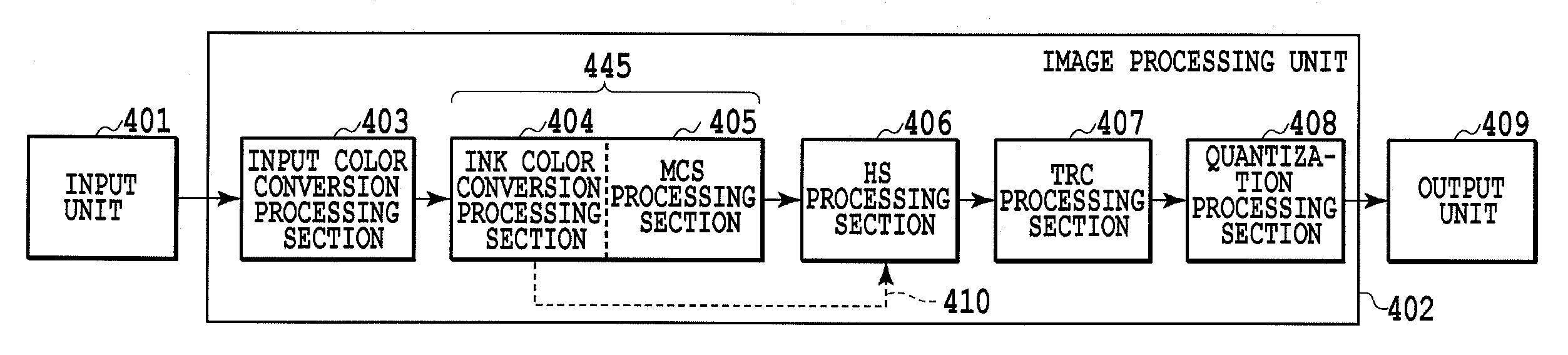
[0127]FIG. 4C is a block diagram illustrating a configuration of an image processing unit according to a second variation of the first embodiment. Generation of a table parameter of the ink color conversion & MCS processing section 445 and processing in the ink color conversion & MCS processing section 445 in the present variation are the same as those illustrated in FIGS. 5A and 5B according to the first embodiment, and a point of difference is that the HS processing section does not perform the head shading. That is, the HS processing is not performed before Step S502 illustrated in FIG. 5A.

[0128]FIGS. 10A and 10B are diagrams illustrating a printing example of measuring images in Step S502 of FIG. 5A according to the present variation. As illustrated in FIG. 10B, the HS processing is not performed at the time of printing the measuring images, and theref...


PUM


Abstract

The present invention is intended to provide an image processor that can reduce color unevenness occurring in a composite color image formed by overlapping different types of inks due to a variation in printing characteristic among a plurality of nozzles while suppressing a reduction in processing speed in generation of printing data. The image processor converts a color signal indicating the image represented by a plurality of elements to a color signal corresponding to the plurality of inks with use of a conversion table determined on the basis of ejection characteristics of nozzle groups corresponding to the plurality of inks so as to suppress color unevenness occurring in a composite color image due to a variation in ejection characteristic among the plurality of nozzles.

Description

BACKGROUND OF THE INVENTION[0001]1. Field of the Invention[0002]The present invention relates to an image processor and an image processing method, and more particularly, to image processing for reducing density unevenness caused by a variation in ejection amount among a plurality of nozzles that eject ink.[0003]2. Description of the Related Art[0004]A printing head used in an inkjet type printer may have a variation in ejection amount among a plurality of nozzles due to manufacturing errors, and the like. If there is such a variation in ejection amount, density unevenness is likely to occur in a printed image.[0005]Conventionally, it is known that, as processing for reducing such density unevenness, a head shading technique as disclosed in Japanese Patent Laid-Open No. H10-013674 (1998) is used. The head shading technique is a technique that corrects image data according to information on an ejection amount of each nozzle. This correction enables the number of finally printed ink d...

Claims


Application Information

Patent Timeline
IPC IPC(8): H04N1/60
CPCH04N1/6041
Inventor ISHIKAWA, TOMOKAZUYAMADA, AKITOSHIGOTO, FUMITAKAIKEDA, TOHRUMIYAKE, NOBUTAKATORIGOE, MAKOTO
Owner CANON KK
Why Eureka
Try Eureka