Method and apparatus for controlling resonant converter output power

a technology of resonant converter and output power, applied in the direction of electric variable regulation, process and machine control, instruments, etc., can solve the problems of reducing the efficiency of the converter, increasing the loss of h-bridge switches,

Active Publication Date: 2012-11-22
ENPHASE ENERGY
View PDF11 Cites 46 Cited by
  • Summary
  • Abstract
  • Description
  • Claims
  • Application Information

AI Technical Summary

Problems solved by technology

As the operating frequency increases, switching losses for the ...

Method used


Image

  • Method and apparatus for controlling resonant converter output power
  • Method and apparatus for controlling resonant converter output power
  • Method and apparatus for controlling resonant converter output power

Examples


Embodiment Construction

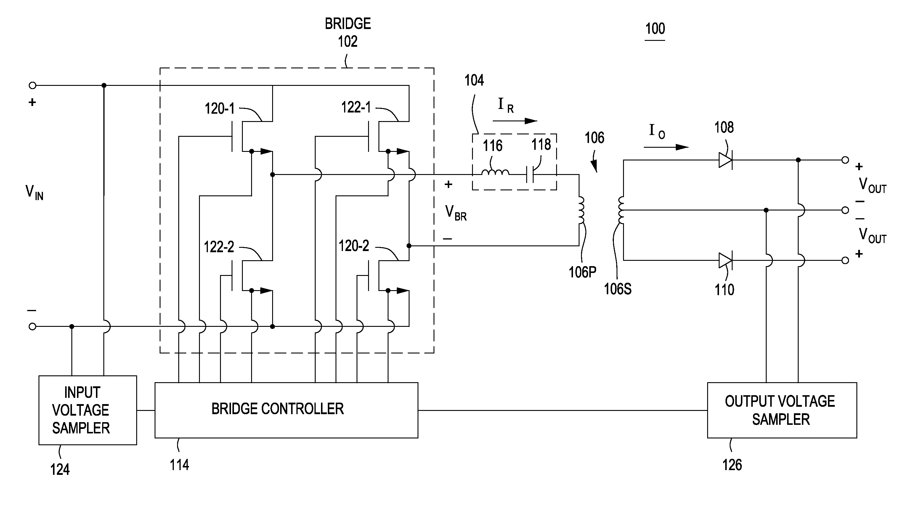
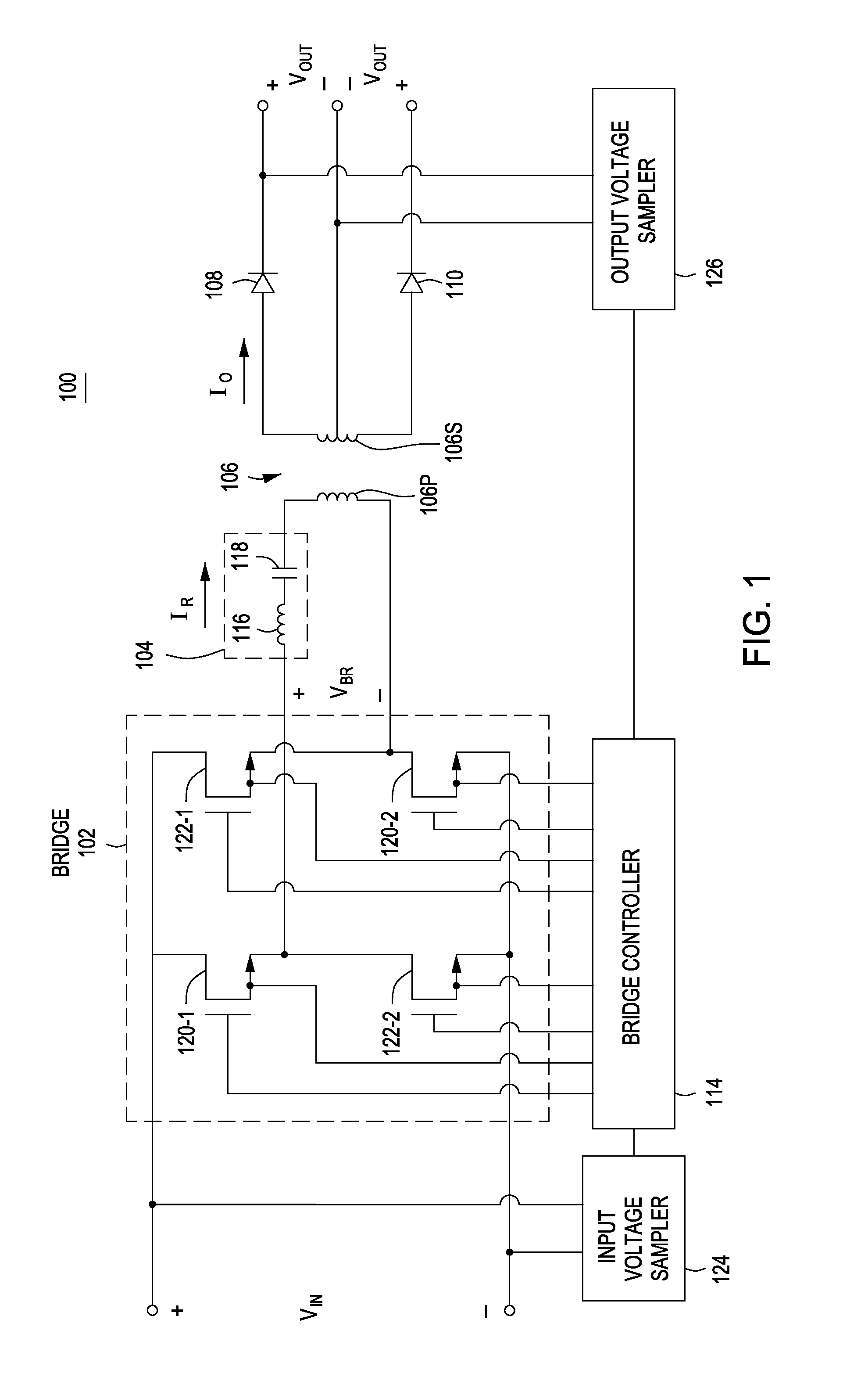
[0014]FIG. 1 is a block diagram of a resonant converter 100 in accordance with one or more embodiments of the present invention. This diagram only portrays one variation of the myriad of possible system configurations. The present invention can function in a variety of power generation environments and systems.

[0015]The resonant converter 100 is a DC-DC converter that comprises a bridge 102 coupled across a series combination of an inductor 116, a capacitor 118, and a primary winding 106p of a transformer 106. The bridge 102 is a full H-bridge comprising switches 120-1, 120-2, 122-1, and 122-2 (e.g., n-type metal-oxide-semiconductor field-effect transistors, or MOSFETs) arranged such that switches 120-1 / 120-2 and 122-1 / 122-2 form first and second diagonals, respectively, of the H-bridge. Gate terminals and source terminals of each of the switches 120-1, 120-2, 122-1, and 122-2 are coupled to a bridge controller 114 for operatively controlling the switches. In other embodiments, the ...


PUM


Abstract

A method and apparatus for controlling power conversion. In one embodiment, the method comprises computing a voltage ratio based on a voltage conversion in a resonant converter; comparing the voltage ratio to a threshold; and controlling, independent of switching frequency of the resonant converter, power output from the resonant converter based on whether the voltage ratio satisfies the threshold.

Description

CROSS-REFERENCE TO RELATED APPLICATIONS[0001]This application claims benefit of U.S. provisional patent application Ser. No. 61 / 519,242, filed May 19, 2011, which is herein incorporated in its entirety by reference.BACKGROUND OF THE INVENTION[0002]1. Field of the Invention[0003]Embodiments of the present disclosure relate generally to power conversion, and, in particular, to controlling power conversion in a resonant converter.[0004]2. Description of the Related Art[0005]Resonant converters provide many advantages over other types of power converters. Such advantages may include low noise, low component stress, low component count, and predictable conduction-dominated losses. Resonant converters may therefore be smaller, less costly, and more efficient devices than other types of converters.[0006]In some resonant converters, a full H-bridge converts a DC input voltage to a square wave voltage as an input to a resonant tank. Generally, the H-bridge is operated at or proximate the res...

Claims


Application Information

Patent Timeline
IPC IPC(8): H02M3/335
CPCH02J1/00Y02B70/1441H02M7/217Y02B70/10G05F1/66
Inventor FORNAGE, MARTINZIMMANCK, DONALD RICHARD
Owner ENPHASE ENERGY
Why Eureka
Try Eureka