Magnetic Attachment Arrangement for Implantable Device

a technology of magnetic attachment and implantable devices, which is applied in the field of permanent magnet arrangement, can solve the problems of not being strong enough to hold the external transmitter housing in the proper position, damage to adjacent tissue in the patient, and magnetic resonance imaging

Inactive Publication Date: 2012-11-22
MED EL ELEKTROMEDIZINISCHE GERAETE GMBH
View PDF8 Cites 58 Cited by
  • Summary
  • Abstract
  • Description
  • Claims
  • Application Information

AI Technical Summary

Problems solved by technology

One problem arises when the patient undergoes Magnetic Resonance Imaging (MRI) examination.
Among other things, this may damage the adjacent tissue in the patient.
In addition, the external magnetic field B from the MRI may reduce or remove the magnetization m of the implant magnet 202 so that it may no longer be strong enough to hold the external transmitter housing in proper position.
The implant magnet 202 may also cause imaging artifacts in the MRI image, there may be induced voltages in the receiving coil, and hearing artifacts due to the interaction of the external magnetic field B of the MRI with the implanted device.
This is especially an issue with MRI field strengths exceeding 1.5 Tesla.
Thus, for existing implant systems with magnet arrangements, it is common to either not permit MRI or at most limit use of MRI to lower field strengths.
But the spherical magnet arrangement requires a relatively large magnet much larger than the thickness of the other components of the implant, thereby increasing the volume occupied by the implant.
This in turn can create its own problems.
This is an additional step during implantation in such applications which can be very challenging or even impossible in case of very young children.
However, there is no suggestion that such therapeutic arrangements might potentially have any utility for magnetic attachment applications such as those described above.

Method used


Image

  • Magnetic Attachment Arrangement for Implantable Device
  • Magnetic Attachment Arrangement for Implantable Device
  • Magnetic Attachment Arrangement for Implantable Device

Examples


Embodiment Construction

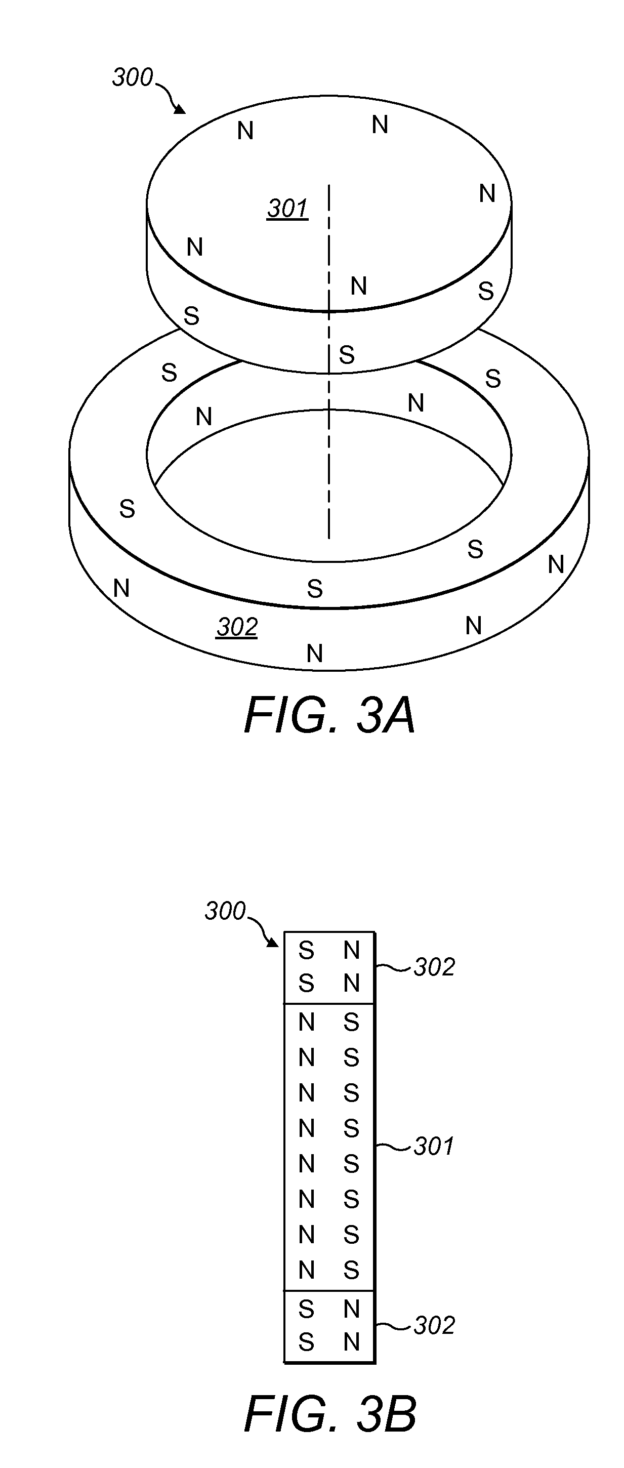
[0019]Various embodiments of the present invention are directed to an improved magnet arrangement for implantable devices in the form of a cylindrical magnet having multiple adjacent magnetic sections wherein at least two of the magnetic sections have opposing magnetic orientations in opposite magnetic directions.

[0020]FIG. 3A shows an exploded elevated view and FIG. 3B shows a side view of an implant magnet arrangement 300 according to embodiments of the present invention. An implantable housing (e.g., implant housing 102) contains a portion of an implantable electronic system. The implantable electronic system may be, for example, a vestibular implant system, a cochlear implant system, a middle ear implant system, or a bone conduction hearing implant system. A cylindrical implant magnet arrangement 300 within the housing includes an inner center disc section 301 having an inner magnetic orientation in an inner magnetic direction, and an outer radial ring section 302 having an oute...


PUM


Abstract

An arrangement is described for an implantable medical system. An implant housing contains a portion of an implantable electronic system and has a planar outer surface adapted to lie parallel to overlying skin in an implanted patient. An implant magnet arrangement is located within the housing and adapted to magnetically interact with a corresponding external magnet in an external device on the skin of the implanted patient over the implant housing. The implant magnet arrangement includes an inner center disc having a magnetic dipole parallel to the planar outer surface of the implant housing with an inner magnetic orientation in an inner magnetic direction, and an outer radial ring having a magnetic dipole parallel to the planar outer surface of the implant housing with an outer magnetic orientation in an outer magnetic direction opposite to the inner magnetic direction.

Description

[0001]This application is a continuation in part of U.S. patent application Ser. No. 13 / 462,931, filed May 3, 2012, which is a divisional of U.S. patent application Ser. No. 12 / 839,887, file Jul. 20, 2010, which in turn claimed priority from U.S. Provisional Patent Application 61 / 227,632, filed Jul. 22, 2009; and this application also is a continuation in part of U.S. patent application Ser. No. 13 / 091,352, filed Apr. 21, 2011, which in turn claims priority from U.S. Provisional Patent Application 61 / 327,158, filed Apr. 23, 2010; all of which are incorporated herein by reference.FIELD OF THE INVENTION[0002]The present invention relates to medical implants, and more specifically to a permanent magnet arrangement for use in such implants.BACKGROUND ART[0003]Some hearing implants such as Middle Ear Implants (MEI's) and Cochlear Implants (CI's) employ attachment magnets in the implantable part and an external part to hold the external part magnetically in place over the implant. For exa...

Claims


Application Information

Patent Timeline
Patent Type & Authority Applications(United States)
IPC IPC(8): A61F11/00H04R25/00
CPCA61N1/36032A61N1/3718H04R2225/67H04R25/606A61N1/375A61N1/36036A61N1/36038A61N1/37518
Inventor BALL, GEOFFREY R.
Owner MED EL ELEKTROMEDIZINISCHE GERAETE GMBH
Why Eureka
Try Eureka