Controlled intermediate bus architecture optimization

a technology of intermediate buses and optimization, applied in the direction of sustainable buildings, dc source parallel operation, instruments, etc., can solve the problems of complex and dependent optimization of the overall system efficiency, and achieve the effect of improving the overall system performan

Inactive Publication Date: 2012-11-22
GENERAL ELECTRIC CO
View PDF17 Cites 32 Cited by
  • Summary
  • Abstract
  • Description
  • Claims
  • Application Information

AI Technical Summary

Benefits of technology

[0006]In one embodiment, the intermediate bus architecture power system includes a bus converter that converts an input voltage into a bus voltage on an intermediate bus, and a point-of-load converter that supplies an output voltage from the bus voltage on the intermediate bus. Additionally, the intermediate bus architecture power system includes a decision engine optimizing controller that controls a system variable to improve an overall system performance ...

Problems solved by technology

Therefore, optimization of the overall system effi...

Method used


Image

  • Controlled intermediate bus architecture optimization
  • Controlled intermediate bus architecture optimization
  • Controlled intermediate bus architecture optimization

Examples


Embodiment Construction

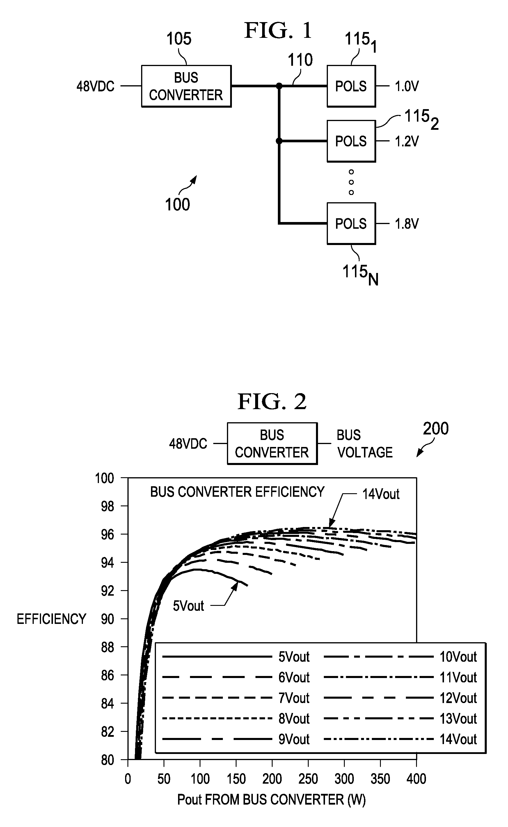
[0022]For DC power systems having power capabilities of at least 50 watts, a bus converter is often used to create an intermediate bus voltage that supplies a plurality of point-of-load converters (POLs), which in turn provide a plurality of output voltages to separate loads. FIG. 1 illustrates a simplified block diagram of an intermediate bus power system, generally designated 100, which may be employed to examine various general characteristics of intermediate bus architectures. The intermediate bus power system 100 includes a bus converter 105 that employs an input voltage (e.g., 48 volts DC) to provide an intermediate bus voltage on an intermediate bus 110. The intermediate bus power system 100 also includes a plurality of POLs 1151-115N that provide N independently regulated DC output voltages (e.g., 1.0 volts, 1.2 volts, etc.), as shown.

[0023]In general, the efficiency of a bus converter will increase as its bus output voltage increases for a constant input voltage. For exampl...


PUM


Abstract

An intermediate bus architecture power system includes a bus converter that converts an input voltage into a bus voltage on an intermediate bus and a point-of-load converter that supplies an output voltage from the bus voltage on the intermediate bus. Additionally, the intermediate bus architecture power system includes a decision engine optimizing controller that controls a system variable to improve an overall system performance based on a monitored system variable or a system constraint. In another aspect, a method of operating an intermediate bus architecture power system includes converting an input voltage into a bus voltage on an intermediate bus and converting the bus voltage on the intermediate bus into an output voltage. The method also includes controlling a system variable to improve overall system performance based on a monitored system variable or a system constraint.

Description

CROSS-REFERENCE TO RELATED APPLICATION[0001]This application claims the benefit of U.S. Provisional Application Ser. No. 61 / 488,440, filed by Vijayan Joseph Thottuvelil, Michael Model, Allen Rozman and Karim Wassef on May 20, 2011, entitled “Bus Conversion System Optimizer”, commonly assigned with this application and incorporated herein by reference.[0002]This application also claims the benefit of U.S. Provisional Application Ser. No. 61 / 488,450, filed by Richard Hock on May 20, 2011, entitled “Controlled Intermediate Bus Architecture For Optimized Efficiency”, commonly assigned with this application and incorporated herein by reference.TECHNICAL FIELD[0003]This application is directed, in general, to power conversion and, more specifically, to an intermediate bus architecture power system and a method of operating an intermediate bus architecture power system.BACKGROUND[0004]Intermediate bus power systems typically include a bus converter that provides a DC bus voltage to a plura...

Claims


Application Information

Patent Timeline
IPC IPC(8): G06F13/14
CPCG06F13/4004H02J1/12H02J2001/008Y02B60/1235H02M2001/007Y02B60/1228H02J1/00H02J1/082Y02D10/00H02M1/007
Inventor THOTTUVELIL, VIJAYAN J.MODEL, MICHAEL J.ROZMAN, ALLEN F.WASSEF, KARIMHOCK, RICHARD
Owner GENERAL ELECTRIC CO
Why Eureka
Try Eureka