Flade duct turbine cooling and power and thermal management

a technology of air duct turbines and turbines, which is applied in the direction of domestic cooling apparatus, turbine/propulsion fuel heating, energy-saving board measures, etc., can solve the problems of engine configuration complexity, engine configuration complexity, and integrated power and cooling systems

Active Publication Date: 2012-11-29
GENERAL ELECTRIC CO
View PDF3 Cites 28 Cited by
  • Summary
  • Abstract
  • Description
  • Claims
  • Application Information

AI Technical Summary

Benefits of technology

The patent describes a system for cooling the components of an aircraft using vapor and air cycles. The system includes an air cycle machine with a compressor and a cooling turbine, along with an intercooler with a heat exchanger. The system also includes a power turbine that is connected to a high-pressure compressor of an aircraft engine. The technical effect of this system is to provide efficient cooling for the aircraft components, which can improve their performance and reliability.

Problems solved by technology

This patent discusses the development of military aircraft engines operating at very high pressures. These engines require cooling air for certain parts, like the turbine blades. Currently, this cooling is often done through the use of fan air, but new designs have been proposed that would benefit from more efficient cooling methods. The technical problem addressed in this patent is how to provide effective cooling without adding too much weight or consuming excessive amounts of fuel.

Method used


Image

  • Flade duct turbine cooling and power and thermal management
  • Flade duct turbine cooling and power and thermal management
  • Flade duct turbine cooling and power and thermal management

Examples


Embodiment Construction

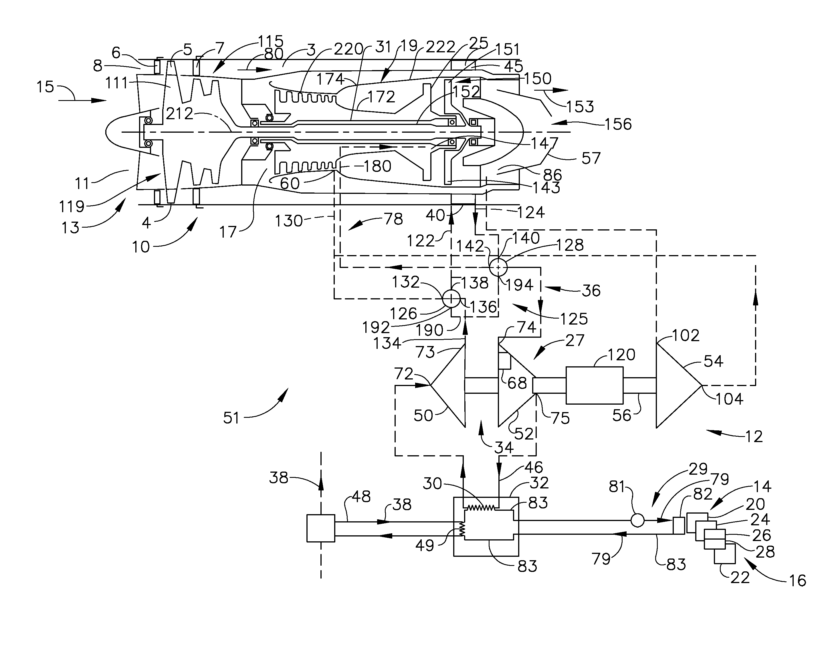
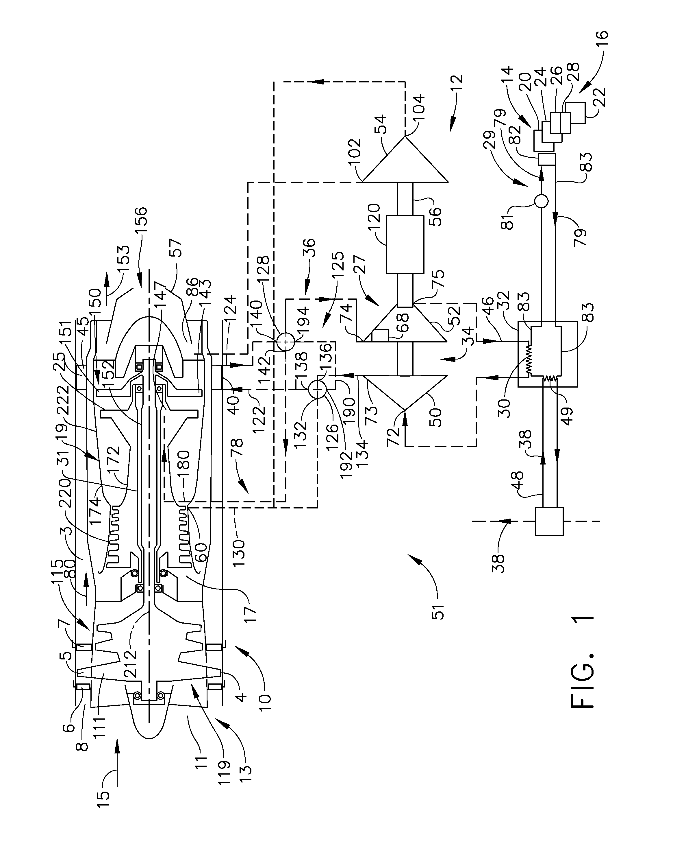
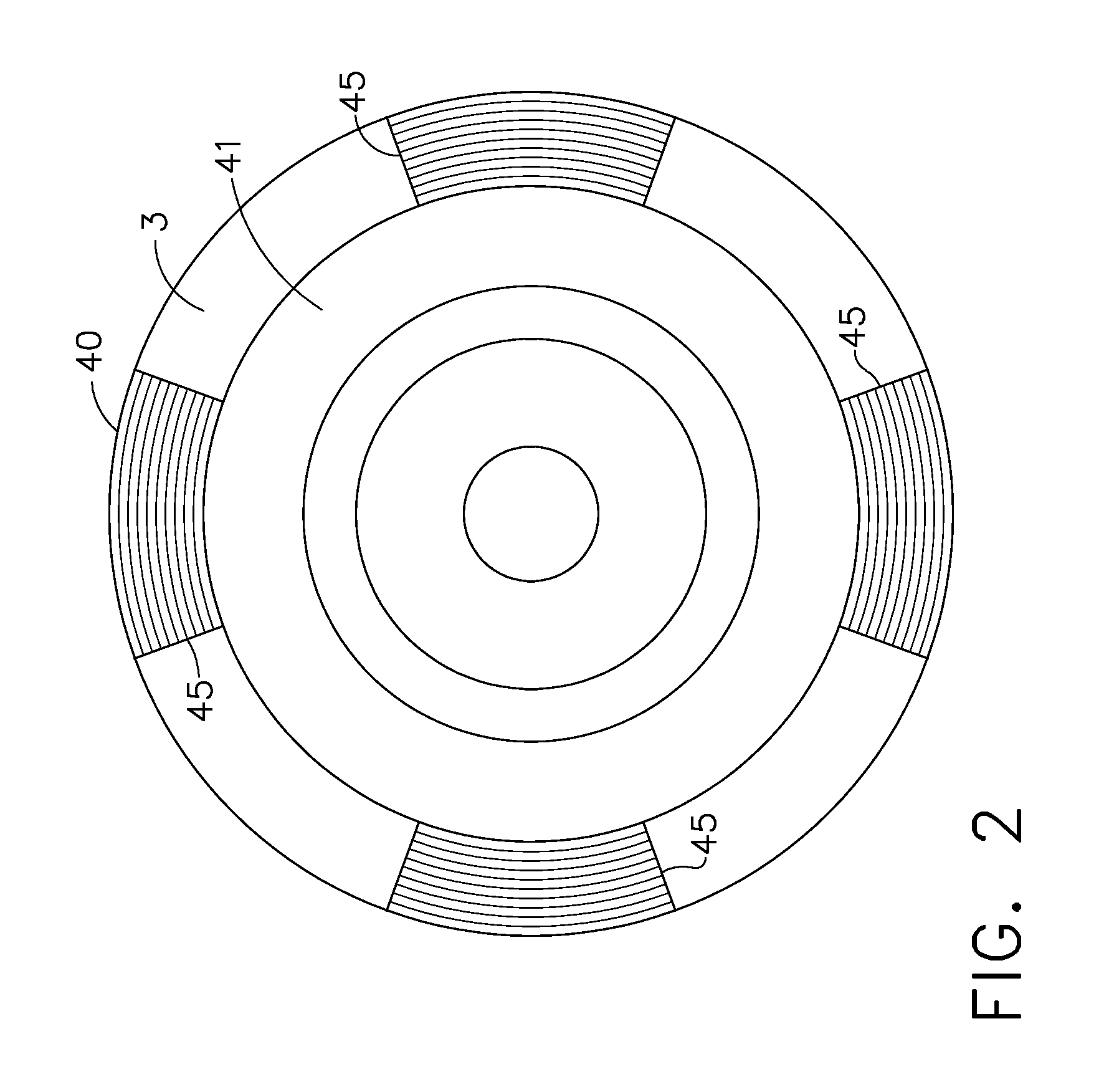
[0020]Illustrated diagrammatically in FIG. 1 is an exemplary aircraft FLADE gas turbine engine 10 including an air to air FLADE duct heat exchanger 40 disposed in a FLADE duct 3 of the engine 10. The heat exchanger 40 may include heat exchanger sections 45 distributed around the FLADE duct 3 as illustrated in FIG. 2. A compound cooling system 51 uses the air to air FLADE duct heat exchanger 40 to alternatively cool compressor air for turbine cooling or cooling air for aircraft component cooling. The compound cooling system 51 is operable to cool hot pressurized bleed air 58 for cooling turbine components in a high pressure turbine 23 of the engine 10 or alternatively switched to cool cooling air 46 for use in an air cycle system 27 used to cool a power thermal management system (PTMS) 12. The pressurized bleed air 58 is bled from a compressor discharge stage 60 of a high pressure compressor 64 of the aircraft gas turbine engines 10. The FLADE duct 3 is a good location for the duct h...


PUM


Abstract

An aircraft compound cooling system includes a power thermal management system for cooling one or more aircraft components, an air cycle system, a vapor cycle system, and a turbine cooling circuit for cooling bleed air and cooling turbine components in a high pressure turbine in the engine.
An air to air FLADE duct heat exchanger is disposed in a FLADE duct of the engine and a valving apparatus is operable for selectively switching the FLADE duct heat exchanger between the turbine cooling circuit and the air cycle system. A vapor cycle system includes a vapor cycle system condenser that may be in heat transfer cooling relationship with the air cycle system. An air cycle system heat exchanger and an engine burn fuel to air heat exchanger in the vapor cycle system condenser may be used for cooling a working fluid in a refrigeration loop of the vapor cycle system.

Description


Claims


Application Information

Patent Timeline
Owner GENERAL ELECTRIC CO
Why Eureka
Try Eureka